Show by Label

Showing posts sorted by relevance for query fft. Sort by date Show all posts

Thursday, September 25, 2025

DIY rebuild of the Tek SG505 Part 3 (final)

This Blog post will detail the third stage of my project to rebuild the Tektronix SG505 instrument.


Here is the link to the post describing the second version of the design: 

https://www.paulvdiyblogs.net/2025/08/diy-rebuild-of-tek-sg505-instrument.html

Here is the first post about this project:

https://www.paulvdiyblogs.net/2025/03/diy-build-of-tek-sg505.html


The reason for the third revision

After the investigations of the second version, I wanted to separate the Power Supply from the Generator in the same enclosure. I also wanted to put the Generator circuits into a full metal enclosure to make the output of the generator as clean as possible and as a minimum, remove the mains hum.
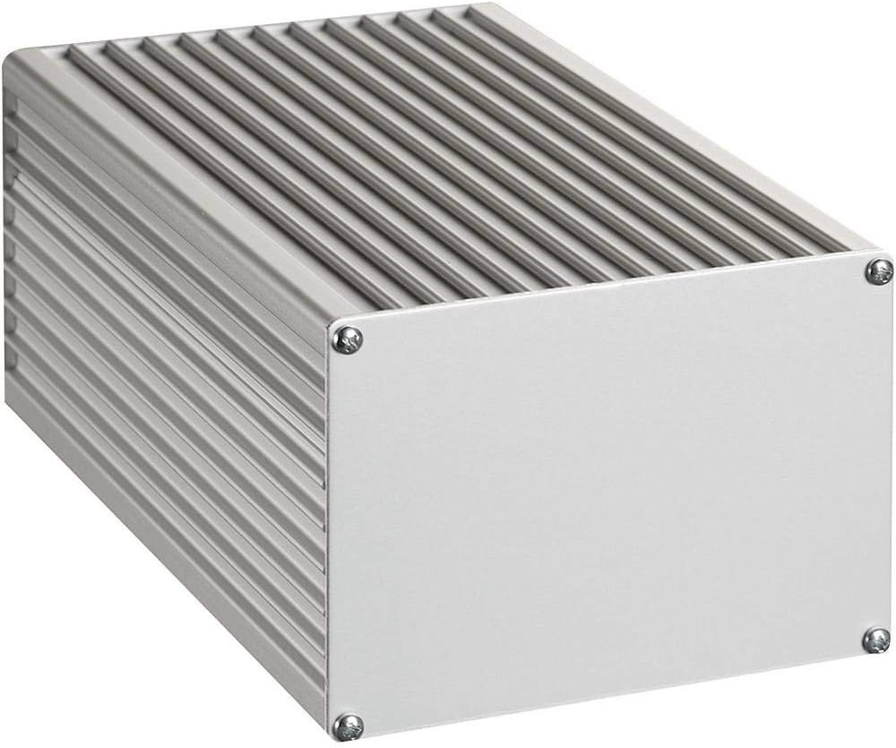


After a very long search, this is the only enclosure I could find that has the required height and width for the front panel layout. It is a ProMa 130 0044 and is also available from Amazon. The outside dimensions are 165x110x80. I would have liked a black enclosure, but alas I couldn't find one. There is one available from ProMa though, with part number 130 0045. I can always spray paint it black myself if I develop the urge. The current Front Panel design will need some modifications and will replace the aluminum panel. The generator PCB will slide in a slot close to the bottom. Unfortunately, the dimensions are a little different so I can't use the current PCB in this enclosure, not even to try it out. 

This all means a new PCB for the Generator, for the Power Supply and for the Front Panel.


Splitting the Power Supply

There will be a separation of the noisy mains related parts of the circuit, that need to go outside of the enclosure for the generator. In essence, it means that the transformer, the bridge rectifier, the main capacitor reservoirs and the 40V regulator need to be on a separate PCB that will be housed outside of the generator.

This part of the project will be described in a dedicated post here:
https://www.paulvdiyblogs.net/2025/11/the-diy-sg505-mains-power-supply.html

The shunt supplies for the +/-16V rails can move to the main generator, and also the 12V supply can move to the main board. They are quiet and will have no negative effect on the generator. I hope. It also makes the interface from the Power Supply enclosure simple, because I will only need to use two wires for the 40V supply that feeds the other three rails.

The circuit after the transformer and the bridge will get some more filtering to avoid mains related noise getting into the generator.


The Power Rails on the Generator PCB

These three rails are very quiet by themselves and can now move to the generator PCB.


(this is not the final version, have a look at the Github site (link below) for the most current information)

No major changes from the previous design, I just added a few extra capacitors and ferrite beads to the power input lines. This may still change a little based on the new layout.

Just when I was about to order the PCB from PCBWay, I decided to skip the idea of using a heat sink for the LM317, because it will still get too hot and raise the temperature in the box. It will now be mounted isolated to the side of the aluminum enclosure.

The Generator circuits

The other circuits stay the same, will just get a revised layout and incorporate the three power rails and needs to fit in the new enclosure.

I finished the new version of the generator PCB, now with the power rails on it.


This is what is ordered. On the bottom part you can see that the LM317 is now flipped around and moved closer to the edge of the board. It will be mounted isolated on the side of the enclosure to remove a considerable heat source.


The Front Panel

This is the updated front panel fitting the new enclosure.

The golden rings around the holes connect the front ground fill to the back ground fill to add an EMI shield to the inside circuits. 


The rings on the back are larger so will connect to the metal parts of the switches, connecting them to the shield. The 4 mounting holes in the corners also have exposed holes on the back and will connect the shield to the aluminum enclosure. 


The enclosure itself is not connected to earth ground but floating. I have created the possibility to connect the GND of the PCB circuits close to the output BNC to an exposed pad on the front panel. In that case, the circuit GND will be connected to earth GND when the BNC is connected to a DSO.


Building up the boards

I received the shipment with the three PCB's and I have built up the power supply by transferring most of the parts from the old board, added the additional parts and tested it. No problems.

The next step was to add the solder paste droplets to the main generator board and transfer the parts one by one from the old board. I used my heat gun to remove them and put them on the new board. When that was done, I reflow soldered the board. Because I used smaller solder paste droplets this time, the reflow process went a lot better, with only a few tiny solder ball bearings and a lot less of the flux gue. I did not clean the board just yet, I wanted to test the functionality first.


Discovering issues

Bad Solder joint

At first I wanted to check the voltage levels of the three power rails. The +16 was only about 9V and then dropped to 3V, the negative 16V was about 30V, the 12V was OK. Although nothing got warm, I quickly shut it off. After connecting the switches and potmeters to the connectors such that the generator could function, I applied power again and saw a welcoming sinewave, albeit with some distortion at the top half. Hmmm, partial good news. When I checked the 16V rails, I still noticed a large unbalance, and that explained the distortion. The good news is that the most complicated circuit seemed to work OK, but the most simple circuit did not, but why?

The hunt for the shunt supply imbalance turned out to become more and more strange. To a point where I started to remove the parts from the shunt supplies one by one, but without any improvement. Using my Lab Supply instead to first power the +16.5V and the -16.5V everything worked, I then supplied the 40V supply, further up-stream and that also showed the correct currents and the system worked fine. Now really puzzled, I used another one of the spare generator boards and started to add the minimum amount of the same parts I just took from the board for the shunt regulator to make it function, which it did flawlessly. Even powering the generator from the second board showed the correct balanced voltages. I was flabbergasted. After thoroughly cleaning the board and resoldering the components back to the board in pairs, everything worked. Bad solder joint!

Wimpy transformer

I also discovered that the mains power supply had a wimpy transformer, so that also needed attention. Details are in the other post: 
https://www.paulvdiyblogs.net/2025/11/the-diy-sg505-mains-power-supply.html


Mistake on the front panel

When putting everything together, I first mounted the construction for the main potmeter and the reduction unit. It fitted perfectly, unlike with the first front panel. So, happy with that result, I added all the other switches and potmeters and proceeded to slide the board into position, when I hit a barrier.

Turns out that I made a serious measurement mistake with the position of the rotary switch for the multiplier. It was bumping to the board and also bumping to the reduction unit. Moving the hole up and left solved that issue, but it will mean another turn of the front panel.

This is how it looks now, so close...


This is the inside view of the now fully working instrument:


Mains related hum

When I did the first FFT tests, I still saw some 50Hz hum and some harmonics. When touching the metal parts of the front panel, it got sometimes worse, sometimes better. I did not have the main potmeter knob mounted, and when I touched the metal axel, the hum got worse. Connecting the Earth GND from the output BNC to the metal parts of the main potmeter and reduction unit with a wire did not do anything, but connecting it to the common GND of the main board reduced the hum dramatically.

It turned out that the mounting holes for the main potmeter support and the reduction unit did not connect the metal parts to the common ground of the PCB. I used star washers on each support to improve that. I also added a blank ring to the layout around one more hole of the contraption to improve that going forward.


Connecting earth GND to common GND?

I intentionally connected the front panel shielding to the metal enclosure to create a Faraday cage, but I separated it from the common GND of the board.  

In my current setup, with the USB connected EMU0202, however, that produced too much unwanted mains related hum. 

I already added a solder tab on the back of the front panel as an option to make the connection possible. When I soldered a wire to it, and connected the other end to a solder lug I added to one of the supports for the main potmeter to connect the two GND's together, it solved the hum issue completely. But now the instrument is earth grounded through the EMU to the laptop, which by the USB-C cable to the power supply is connected to earth GND.

The other possible connection for the instrument to get earth GND connected is through a BNC cable to a CRT or DSO and that will connect it to earth GND as well.

The original SG505 has a switch to connect the common GND to earth GND. If you also want to have the option to separate or connect the enclosure from earth GND, you could add a toggle switch to the back of the unit, or a sliding switch on the side. I'm undecided at this moment, but it's easy to add afterwards.


Result after the fixes

After all these mishaps and corrections, I wanted to share the first FFT from the generator, hot of the press. Note that I was able to quickly trim the second Harmonic visually into oblivion (0.00002%).


Result, no hum, no noise. 

Unfortunately, with H2 visually gone, H3 is now sticking out, but the rest of the harmonics are virtually invisible. 

During my testing with the updated power supply and mounting everything on the front panel a few times while fixing things, I noticed that I could no longer adjust the H2 harmonic as low as it was above. There is now also some hum visible, so when the new supply arrives, I will look at it again in more detail. 

Just for reference, my DIY version of the generator seems a bit better than the original one. Albeit using different measurement tools.


I'm almost there...

Building the final version

Happy with all these results, I uploaded the updated power supply V4 and the updated front panel to PCBWay for production. They gracefully continue to sponsor my activities, despite my screw-ups.😇

It will usually take about a week for the shipment to arrive.

I got the front panel, but made a mistake ordering the power supply board, so that will come in another week. See the dedicated Blog post for that part of the project here. 

In the meantime, I started working on the various BOM's, including an off-board one for the front panel parts. They, and all other information will be on my Github site that I will publish when I'm done. 

I have been using a lot of parts I already had, but needed to find parts that I could put on the BOM so others can order them. Here are some details for the off-board parts.

Output signal potmeter

One of the challenges was to find a potmeter for the output volume with a switch, that is activated at the end of the rotation. Most of the ones I found switch at the beginning, at 50 degrees according to the specifications.

I put one together with parts I had from a previous life, and that looks like this:


These potmeters come in separate segments you can take apart so you can create stereo versions, or use two different resistor values, and optionally also add a switch segment. I was able to turn the switch segment around to get the right action. To have the switching indent at the end of the range is more natural, because the switch fixes the generator output by a resistor divider just below the maximum output. This is also how the original SG505 has it. I put a potmeter in the BOM with a SPDT switch, but it will be activated in the beginning of the rotation. If you are able to find a potmeter with the switch activated at the end of the rotation, let me know in a PM so I can share it with others.

Mounting the main board

You can add all the components on the main board, but do not solder the 12V regulator in position yet. The height of the regulator to the board needs to be determined first. 

It's now time to mount the main potmeter and the reduction unit using metal brackets to fix the position of the axel in the middle of the hole of the front panel. Add a solder lug on the screw that fixes the reduction unit with the screw hole that has an exposed ring on the bottom of the PCB. The is the one closest to output on/off switch connector. Lightly tighten the screws and nuts and try the position of the whole contraption with the hole in the front panel. When you're happy, see if you can tighten the nuts while the PCB is still on position. If not, you need to carefully slide the PCB a few cm out of the enclosure slots such that you have access to the screws on the bottom. Fix everything and try it again.

When that is done, you should have the main board flush to the front panel, with the potmeter axel in the middle of the hole. 

To mount and fix the 12V regulator, we need to drill a 3.5mm hole in the side of the enclosure to give it a good heat sink. Position a sticker on the inside of the enclosure about in the position where the regulator will be. My hole was drilled in the middle of the third rib from the bottom. The hole should be drilled the middle of that cooling rib, because the head of the screw need to be in the center between the ribs. Position the main PCB in position, such that it will be flush with the front panel. Put the LM317 in position after you have clipped a few mm from the legs so they don't connect to the bottom. With the regulator inserted in the PCB, note the position of the hole and mark it on the sticker. Use a caliper to measure the distance from the front edge of the enclosure to where you marked the center of the hole of the LM317. Transfer that measurement to the outside and mark the position in the middle of the rib. Remove the main board and drill a 3.5mm hole in the enclosure. Grate the hole on the inside so there is no burr. Slide the main board in position again, and maneuver the hole of the LM317 to align with the hole in the enclosure. use a screw and nut to position the LM317 and solder one or all of the pins to the regulator when it is in the correct position. Remove the screw and carefully slide the main board out of the enclosure. You can now permanently solder all three pins to the main board. 

Important! When you will fully mount the regulator later, (not now) you have to use an isolation pad (mica or silicon) and a plastic isolation ring to make sure the metal pad of the LM317 is fully isolated from the enclosure, or you will have a dead short of the supply rails.

Fixing the OLED display to the front panel

Do not mount any of the other parts to the front panel yet. It allows you to handle it and the fragile display easier. 

I first used a black permanent marker to color the inside of the rectangle in the panel pitch black. Do that from the inside so you don't smear ink on the face side. 

Make sure you can power the display from the main board while positioning it so you can see where the text is, relative to the viewing area. It will be virtually impossible to position it correctly otherwise. If your main generator board is not inside the enclosure with the 12V regulator cooled by it, you have to use an external heat sink, because the regulator will get too hot otherwise.

Using glue

You can try to glue the OLED display in position to the new front panel. You need to add some glue (not instant glue) sparingly(!) so it does not flow into the visible area when you gently(!) press the two together. Add the glue on the front panel backside. Power the display so you can see what needs to be visible and position it horizontally, put it in position, and keep it there until the glue is dry enough.  I first tried that, but abandoned it.

What not to do

In my earlier glue attempt, I used a washing cloth clamp to secure the OLED display in position when letting the glue harden. We'll that seemed to have destroyed the display because it turned black. I first thought that the clamp must have pressed too hard and damaged the flexible cable connection between the glass and the PCB. I had no spares so needed to order a new display. 

Well, after the new display's arrived, none of them worked. Tongue in cheek and red faced I have to admit that it wasn't the display. While trouble shooting, I measured the SDA and CLK signals with my DSO and I measured 5V on the display PCB with my DMM, so I started on a rat race trying to find the issue. After a while searching, it turned out that the crimping of the GND wire on one side of the interconnect cable was bad and must have disconnected while I was clamping to let the glue dry. Although visually the crimping looked OK and I did not look further, but searched for other causes. Long story short, what I did wrong was that I connected the GND of my DMM to a GND pin on the main PCB, in effect bypassing the bad GND wire connection when measuring the 5V. I did the same with my DSO, but that still showed the presence of signals so I did not look further. I replaced the GND wire in the extension cable and did a better job crimping the connecter and all is well again.

In hindsight, it's probably safer to use some normal Scotch tape to keep the OLED display in position while the glue is drying. Or, don't use the glue method at all. 


Using Scotch tape

I ended up using Scotch tape to secure the display, I used electrical tape earlier but that's too flexible and the display sagged down a bit. 

In the picture below, I used another PCB on top of the front panel so I could position the OLED board better. In my case, the distance between the top of the OLED board and the top of the front panel was 20.78mm. You can easily check the horizontal adjustment that way by sliding the display horizontally into position. Because I used clamps to press the two boards together, I could rather easily adjust the vertical and horizontal position of the OLED display within the rectangle opening. To do that you have to power the OLED display from the main board so you can see where the text is.


After positioning the display with one piece of tape while positioning it, I used some more Scotch tape to finally secure it in position. Do not cover the onboard regulator with tape. I used a piece of double sided foam tape to bridge the distance to the front panel en the OLED display where the connector is. It should help with the stress put on the rather flimsy OLED board sandwich with the glass display when you plug the connector in.


It does not look very pretty, but does the job and is not permanent.


Assembling the front panel

Do not fasten the front panel to the enclosure just yet. First mount the switches with their cable harnesses already in place, with the solder ends shrink-wrapped for sturdiness. Ask me why. Mount the Vernier potmeter and the volume potmeter. Solder an about 8-10cm thick ground wire to the solder pad on the back of the front panel, with the wire going upwards. 

Mount the rotary switch into position with the connected wires on the top side, away from the main board.

Get the front panel roughly in position to the enclosure with the main board already in place. Solder the other side of the ground wire to a solder lug you should have installed on one of the mounting screws of the potmeter delay unit.  Take one of the screws that have a ground ring on the bottom so there is a solid ground connection. Check with an Ohm meter for only a few Ohms max. between the front panel exposed holes to one of the GND test pins on the main board and the outer ring of the BNC connector.

You can now connect the wire harnesses from the 0/-10dB switch to their locations. The wiggling room is very tight which is why it should be clear by now that you should not have fully mounted the front panel yet.  Then connect the output on/off switch connector. At this point, make sure the switch operation is correct, because you can still turn them 180 degrees to fix that. The other connections are not critical, so you can now mount the front panel into position with the two screws going into the bottom half of the enclosure.

You can now add the ring and nut for the BNC connector and tighten it lightly such that the main board is flush against the front panel. You should have tried this position already when you mounted the voltage regulator to the side of the enclosure such that you don't put too much force on the leads of the LM317. With the front panel mounted, you can now also mount the LM317 into position. Remember to not forget the isolation! Double check again that the metal tab is indeed isolated from the enclosure.

You can now connect all the other wire harness connectors and add the knobs into position.


Calibration procedure

Now it's time to add power and check all controls and that the switches are in the correct working position.

By now, you should have a sinewave output and the counter should show the frequency. If all the controls work correctly, it's time to let the unit warm-up for at least 15 minutes. After that, it's time to finely adjust the 44V main rail, while measuring the voltage on the main board using the +Vreg and -Vreg test points. Adjust the rail voltage with the trimmer on the main power supply board.

With that done, you can now verify the voltages of the +17V and -17V rails. They should be within 0.5V of each other and 17V +/- 100mV. If not, you can change the resistors that are setting the voltage for the TL431's. If you installed the optional trimmers, you can set both rails as close as you can to +/-17V and equal to each other.

To adjust the 2nd harmonic adjustment, you need to use an FFT to see the effect. With the unit now sufficiently warmed-up and the rails adjusted, you can trim the 2nd H trimmer for a minimum height or dB value. You probably have to use some averaging of the measurement to see it well.

Now we can calibrate the 0dB output level. Select the 0dB output level with the switch. Select the Cal position switch setting on the output potmeter. Connect the output of the generator through a 600 Ohm in-line terminator to a DMM in the AC mode. Select the 1KHz frequency on the generator, because the DMM will most likely be precise at this frequency. Adjust RV2, the 0dBm adj. trimmer for a reading of 0.77459Vrms or 0dB.

Verify that the -10dB output switch setting results in about 0.24494Vrms or -10dB. 

Change the output value potmeter out of the calibration setting, and verify that you can adjust the output from just over 1.0Vrms down to 300mVrms.

With a 1.000KHz frequency output in the X1K range, and the Freq Vernier in the middle, verify that the Freq Vernier setting has a range of at least +/- 10Hz from the set frequency or 20Hz in total.

Verify that switching to the X100 range shows a frequency of 100Hz +/- 5%. Switch to the X10 range and verify that the frequency is 10Hz +/- 5%. Switch to the X1K setting and verify that the frequency is 100KHz +/- 5%. If not in that range, you can change the value of C19 and C26, but make sure they are matched in value.


That concludes the calibration and verification of the unit.


Final steps

In the meantime, the new power supply boards arrived and I built one up. The details can be found here.

I now have a fully functioning setup and will show some more measurements soon.


Final results

After a complete calibration and verification, below is the final result. The cover is on, and there is no difference with the frequency counter on or off.


H2 is 0.000048%.
H3 is 0.00031%
H5 is 0.000025%
H6 is 0.000024%

Total THD is 0.00033%, THD+N is 0.0024%
No mains related hum.

I think this is not bad at all, and using my tools, it seems even better than the original.

It took a while, but in the end, I'm very happy with the result.

I added this project to the Shared Project on the PCBWay website so others can easily participate:
Shared Project DIY SG505
Shared Project DIY SG505 Power Supply

Because I think this is an interesting instrument to have on your bench, I also added it to the yearly PCBWay contest that will give it some more visibility.


Here is the setup on my instrument bench:


The top shelf has the actual instruments. From left to right: the DC Dynamic Load, the SG505, my frequency counter, and the GPSDO on top of the master clock, the rest is out of sight) BTW, these are all instruments that are listed on my Blog. Below that shelf is room for the supporting stuff, like the power supplies.


There is a Github project with all the information you need to build this instrument.


Friday, April 18, 2025

The SuperReg Power Supply

This will be a post to describe my efforts to more or less regurgitate and resurrect the Walt Jung/Jan Didden power supply design that gained a reputation as a SuperReg.

I wanted to use this supply for my SG505 project because it deserves and will hopefully get a very quiet and responsive power supply.


A lot has been written about this design over several decades, and many attempts have been made to improve on it, mostly for audio applications. The majority, at least the ones I found, were tailored to hi-end audio power amplifiers, with an obvious focus on supplying lots of power. I need less than 100mA for both rails, which is more in line with pre-amps, DAC's etc. For these type of applications the original design from Walt Jung is more than sufficient. It does not need a lot of special parts, and is deceivingly simple.

The secret to success is to stay close to the original design principles as much as possible, which is what I'm planning to do.

If you want to have some more background on the original Superreg design, the performance measurements and the evolution over time, here is a link with all the information that will keep you busy for a while. SuperRegs  Here is another link to the articles from Walt Jung: directory

I will follow the latest version (2.3) and try to replicated that. The information can be found in the above archive, but this is the document I'm using as the reference for my copy. Version2.3
Here is another refinement/update for the reference: article
If you're interested in buying the original PCB's, you can do that here.

And finally, there is a discussion at diyaudio.com that can be followed here.


Below is a picture of the V2.3 PCB that Jan Didden designed.


I'm going to use SMD components where possible, hopefully without messing-up, and create a version with +17V and -17V outputs and also add the +5V rail I need.

Here is the schematic design I came up with:


Even though I'm hesitant to deviate from the original, there are a few required differences with the original. 

First of all, I added the rectification and reservoir capacitors. This means that I only need to feed two AC transformer winding connections, and leave the transformer, on-off switch, and the EMI filters in another separate enclosure, away from the more sensitive parts.

Because I need to make some changes, I used 499R for R4 and 5K1 for R5 because I'm also not going to use the LM329. It's only available in TO92, and it's pretty expensive. The 4K99 value will cause a current in the Zener of about 2mA. According to the specifications, the device also works with 1mA. However, the recommended combined Zener current by Walt should be around 4mA, so the value for R5/R12 should be 2K7 which sets the current to 3.8mA. The schematic still has the 5K1 value though because I'm not sure yet that I need that much current.

The original information by Walt Jung in the first article about the Superreg also talks about the 499 Ohm for R4 as having the same value as the parallel value of R7 and R6, both 1K, (to better balance the load on the Opamp inputs). The value for the 4K99 most likely comes from a very early version of the supply, called the Sulzer regulator, shown in figure 7a and 7b, in Walt's first document. In that version they use 51K for R5 and R10 (now R12) in those schematics. The voltage setting resistors (R4, R3 and R9 and R8) were 3K16 each. In a newer version, Walt used lower values for these resistors to improve the regulator. My assumption is that he used a factor of 10 to lower the values, and he used wire-wound metal film THT resistors that were only available in the 4K99 value.  

Because I'm going to deviate from the LM329 by using the recommended combination by Walt of two Zener diodes in a back-to-back configuration to keep the noise and the tempco down. It's an old trick to use a normal diode in a back-to-back configuration with Zener, because the tempco's of both cancel each other out. On top of that, a 6V3 Zener is typically at the sweet spot of the tempco for Zener diodes.  I also need an output of +17V. So the voltage output divider values of R6 and R7 have to change. 

In one of the articles from 2/95, there is a table 1 on page 31 that shows different resistor values for different output voltages. There is a 16V and a 18V row, but not a 17V one. In all cases, R1 is 499 Ohm, just as I want to use. I wanted R7 and R14 to stay close to the 1K value to keep the Opamp balance almost the same with the 499R value of R4 and R11, so I selected a 820R value, which is just about in the middle for the recommended 16V (866R) and 18V (806R) outputs.
To get the +/-17V (+/-1%) output voltage with E24 values, I needed to use a trimming resistor, so R6a has a companion of R6b, the same as with R13a/b. 
The formula to calculate the resistor values is :  Vout = Vref x (1+ (R4/R3))

This means that we need a 1K25 value for R6 and R13 with the 6V9 reference (although that value needs to be confirmed), see actual measured values below.

The parallel combination of R6 and R7 with these values is 495 Ohm which dictates R4 to be 495 Ohm as well. Keeping the 499 Ohm value should be good enough initially, but can be changed later on.

The recommended Opamp is the AD825, Jan Didden mentioned that the NE5534 can be used, or even has to be used for higher supply output voltages anyway, and since I already use them in the SG505, I might as well use them here too. They are a lot less expensive at 1/10th the price of the AD825. You could swap them out if you want as long as you use an SOIC package. I also ordered two AD825's which I'm going to use first.

Most of the parts are SMD, with the exception of the larger capacity electrolytes, and the 10nF film capacitors for the rectifying bridges.

It seems that Walt very carefully selected the series transistors, the D44H11/D45H11 so I'm going to use them too. They are not expensive.
The bias transistors for the series transistors I'm using are the equivalent SMD versions of the BC546/556 TO-92 version.

Because the required output is +/-17V, I raised the voltage for the series Zener diodes (D2 and D7) to 7V5, to keep the Opamp output just about centered within the rail voltage, as is recommended. The Zener values are not overly critical, I just happen to have this value in stock.

Note that the recommended Panasonic HFQ series for the 120uF/35V electrolytes have been discontinued for a very long time, so I selected decent quality replacements.

I will need small heatsinks, so I will not put a footprint on the PCB, just use the U-shape parts that you can screw on the TO-220 package.

I've also added the +5V section, and tried to keep that out of the way of the other two supplies as much as possible. That's why I tap the AC inputs from both transformer windings, the keep them balanced and separate the two supplies at the AC level, and also create a "digital" GND for the Arduino Nano and the relays I will use with the next version of the generator.


The layout is now done, and the request for sponsoring from PCBway for the production and shipment has been done. They generously support my activities so I can spend the money on parts.


Don't worry about the apparently reversed picture of the terminal blocks, they will be installed correctly. (;-))

The parts and the PCB arrived and I quickly put together a working version, again using my new reflow hotplate.


When I first powered it up and checked the output rails, I was pleasantly surprised with a +/-18.9V output. This is without the trimmer resistors. 

However, when I tested the +5V supply I was greeted with a 0V output. Bummer! On careful inspection, I spotted my mistake. I was planning all along to tie all the common grounds to the GND pin of the output BNC. When I was testing the supply, the digital GND for the +5V was still floating and not connected to either common. Well that makes sense. However, when I thought about it some more, I realized that I did not need to connect the digital or DGND to the analog common GND's. I could keep the digital supply completely separate because it will only power the Arduino Nano with the OLED display, and the relays I'm planning to use for the range switching. I could keep all of that "out of the way" from the generator by creating a dedicated and separate DGND. That required a small modification of two diodes and two 10nF capacitors to tap the other two windings and create a negative return path.

While making the changes to the schematic, we now have a V1.1:


Note that the two Opamps are still shown as the NE5534, but I installed the AD825. (KiCad does not have a symbol for it so I'm leaving the NE5534 as a place holder)

The two optional diodes and two filter caps for the separate +5V supply DGND are added underneath the board.

First step now is to tune the voltage rails.
I first measured the Zener diode combination. The plus supply was 6V99 and the minus supply was 7V01. They are very close to each other. When I used a 6K2 trimming resistor for R6b1 and R13b1, the voltages after warming up are now +17V04 and -17V04. Excellent!

The parallel resistance of the 1K3 and the 6K2 are now 1K075, very close to the original 1K. 1K075 in parallel to 820R makes 466 Ohm, I could lower the 499 to 470 Ohm to better balance the Opamp inputs but I'm going to leave the 499 Ohm as is for the time being.

The downside of using hi-efficiency SMD LED's for the current source is that they are very, very bright. I think that I'm going to use a black pen to darken them a bit.


I used my thermal IR camera, and was surprised to see that the current source transistor (Q2) was getting a lot warmer than I anticipated. I am using the SMD version instead of the original TO-92, but even so. There is 1.97V across R1, so with 240 Ohm, that's 8mA of current. The earlier version (Fig 8a and 8b) used a 100 Ohm value that Jan Didden changed to a 249 value. I used a standard 240 Ohm value.


To the right is the positive supply with the (hot) 330 Ohm load, to the left is the negative supply with no load. The green LED's are also contributing to the hot spots on the display.

Even without a load, the voltage differential with an input voltage of 36V across the series transistor makes them warmer than I had anticipated. (you can easily see the difference between the left unloaded and right loaded versions)

With a 330 Ohm 1W resistor as a 50mA load, the series transistor gets a little warm but not overly so. Because the generator setup I have now will only need about half of that current, this will be OK. If not, I can use a larger heatsink.

Next step is to make an FFT of the outputs to see how quiet they hopefully are.


This is the positive supply, also with a 330 Ohm/50mA load. Can you believe that I checked and double checked my measurements? This is unbelievable, wow! There is no difference with a shorted input lead, so the supply does not add anything it seems.
With the 50mA load, the input to the regulator has a 1Vp-p mains ripple, that's completely gone, and no harmonics or noise. Too good to be true? 

I was planning to use a mains input filter, I'm reconsidering that for the moment. Even in my noisy environment, there is nothing to worry about.

Here is the negative supply:


Walt, I'm mightily impressed, hats off for your design.

I was already formulating plans to modify the +/-17V supplies to a shunt version that Walt published in a later document, to separate the raw DC side even more, but that is not needed in my case.

And now the final test, the generator with the new supply:


A very clean output with only a tiny bit of mains related harmonics on the left.
I do not really trust the measured and reported THD+N number of 0.0056%, but visually, it looks great with only a tiny third harmonic spike visible, and this is still without any shielding whatsoever.

This power supply is great and that part of my problem is solved!


The +5 Volt circuit

I'm going to hi-jack this SuperReg post by showing information about the +5V circuit I added. It has nothing to do with the SuperReg, but I'm adding that adventure here because I put it on the same PCB.

Here is the FFT from the loaded +5V supply with the positive and negative still loaded with the 50mA:


This is with a 51R resistor for 100mA load. The 50Hz mains harmonics comes through but is otherwise very clean as well. Even when I extend the measurement to 100KHz, there is an uptick in the noise floor after 30KHz, but no additional hash. 


But...
When I connect the Arduino counter circuit to the +5V supply, I get this...


My solution to create a 5V rail is causing an issue, and with it, the transformer gets very hot so something is very wrong with my design. The diodes must be shortening the two transformer windings or something like that.
The Arduino only draws 14mA, that's not the problem. I need to figure that out.

I now modified the 5V input by tapping only the transformer winding for the positive section, by using two diodes. Of course, the three power supplies still get GND connected on the generator PCB, because I need to tap the sinewave as an input to the counter. Now that I don't connect the two windings of the transformer, there is no current flowing between them anymore, and the transformer stays cool. That part of the problem is solved, but I'm not there yet.

Here is the new schematic V1.1a:


This is the still disappointing result:


A bit better, but no success whatsoever. There are two possible solutions I can think of. One is to galvanically separate the pick-up for the counter from the generator, by using a pretty fast opto-coupler. The other possible solution is to use a separate transformer for the 5V supply. That's the easiest solution to try.

Here I'm using a separate 12VDC Wallwart just to give it a quick shot. I also tried my Lab Supply with an 8VDC input, with the same results.


A lot better, but not good enough yet. It proves to me that I need to galvanically separate the output amplifier of the generator going to the Arduino counter.

Here is also evidence why I don't trust the THD+N results from the software. You can clearly see more harmonics, but with a better result than the earlier 0.0056% ???

I'm now using an H11L1M opto-isolator, that has an internal amplifier and Schmitt-trigger gate. In order to get enough signal drive for the transmitter, I had to bridge out the output capacitor that you can see in the amplifier circuit above. That works, so the counter is functioning again. However, there are still added harmonics. The solution I think is to use an additional output amplifier buffer, solely for the counter input. As long as it produces a logic level signal, the opto-coupler will be happy.

Here is the result with a hodge-podge of wires and an additional protoboard to test the opto-coupler:


Getting better, but I'm not happy yet. If it turns out that driving the transmitter is causing the added harmonics, I will need to reconsider if I want to continue with the counter. (PS this time the THD+N is more realistic I think. Go figure...)

As a next step, I created a simple sine wave to square wave amplifier and let that drive the opto-coupler to create more isolation with the generator. Now we're finally getting there:


Here is the amplifier section with the circuit to connect to the Arduino Nano:


I'm done with this post for now, and will continue with the SG505 post.

I have purchased another transformer for the SuperReg that I will try later on. It has a copper shield around the windings that can be connected to Earth GND for extra shielding:


Plan to update to a new version

I like this SuperReg very much but because I made a mess with the +5V supply I may create a new version 1.1 that removes that circuit and only has the positive and negative supplies on it. When I do, I will create the layout such that these two sections can be easily separated so you can use them individually, and use one extra side to create another supply. To apply the lessons learned, make it more universal and also support higher currents, I will allow space for larger electrolyte smoothing caps for the raw DC supply, create a bit of a PCB heat-sink for the current source, create room for larger heatsinks for the series transistors and provide a ground plane while keeping the "star" GND connections. Don't hold your breath though, I will wait with the redesign until I have a project that needs it.


I'm not using it for the SG505 project anymore

During the design process for the DIY SG505 rebuild, where the above supply was intended to be used, I decided that this supply was a little over-kill for that project so I decided to create a smaller and more dedicated shunt supply.
That process is explained in the DIY SG505 V2 and V3 Blog posts:


Tuesday, May 19, 2015

Building a Simple 1KHz Distortion Analysis Tool (upgraded)


(above is the new third and updated generation. Twin-T on top, below it the Victor 1KHz reference oscillator, sitting on top of the heavily modified EM-U 0202 USB "sound card")

For my audio projects, I wanted to have a method of simply measuring distortion without buying (too costly) or building a (too complex) full-blown analyzer.

I started out with a very low distortion 1KHz sine wave generator and a Twin-T filter, and put them in the same enclosure.

This is the old and first instrument.


The low distortion sine wave generator is to feed the DUT, and at the output, use a filter to supress the sine wave again. What is left should be the distortion created by the DUT and some additional noise.

The components

As it turns out, designing a very low distortion since wave generator is not that easy. Luckily I found a unit that is excellent for a reasonable price. It is called the Mickevich (the designer) Ultra Low Distortion  (<0.00001%) 1 KHz Sine Wave Generator.

What was left was to design a precise filter, the required power supply and the box to put it all in to.

In addition, I needed an external sound card interface that is used as a digitizing front-end for the PC-based FFT analyzer.

I described this project on a diyaudio forum where much more information can be found about the oscillator, and the filter I used : http://www.diyaudio.com/forums/equipment-tools/252751-simpel-1-2-diy-1khz-distortion-analysis-tool.html 

When I picked-up my electronics hobby again after I retired (early), this was one of the very first projects while learning the "trade" again. I wanted this tool because at the time, I was designing and building battery operated headphone amplifiers to be used on a plane. 

In 2022, I decided to describe the unit here in more detail, so I'm not depending on the diyaudio Forum. I also decided it was time to design a PCB and use better components for the filter, as they were recommended on the Forum.


The Ultra Low Distortion Oscillator

In order to make good measurments you need to have a very low distortion sine wave oscillator. I found the Victor Mickevics design and purchased one for 1 KHz.
Look for details of an improved version here: Info


Victor uses a novel application of the traditional JFET-based AGC design with a deceivingly simple but oh so clever detection, rectification circuit with standard parts to get astounding results.

The results for this little board are stunningly good. Here it is measured with non-professional equipment and that shows only 0.0003% THD and 0.0024% THD+N. The actual specifications are even better with second harmonic at -136 dB (0.15 ppm) and third harmonics so low it cannot be measured (< -140 dB).


Unfortunately, it seems Victor is no longer active and selling them on eBay, but you can still contact him by email and ask for his products.

The Twin-T Notch Filter


The Twin-T notch filter is based on a simplified design from Dick Moore (richiem) here are the details
I tailored his design for just a single 1 KHz operation.

Here are the schematics that I put together for the combined instrument:

The power supply

The sine wave oscillator needs about 35VDC or a little higher, to create a +/- 15V.
The Twin-T also needs +/- 15V, but I didn't want to use the supply already on the oscillator. I did not want to disturb it.


This supply feeds the 1KHz oscillator with about 34VDC and the Twin-T notch filter with a balanced +/- 15V supply.

As I typically do, I use a separate AC transformer outside of the box, to avoid mains hum etc. When I was winter birding in Texas, I purchased a Rainbird 24VAC wall-wart transformer, alas that was only for 115V.

Back in Europe, I use a 12-0-12VAC transformer for several projects, so I used the 24VAC to feed the power supply.

Because Victor's oscillator needs 35VDC, I could use a full bridge rectifier and an LM317 and keep things cool, rather than using a doubler and deal with 70VDC as input to the LM317. They will get hot, causing temperature related drifts to the oscillator. I also did not want to "steal" the +/- 15V coming from Victor's oscillator to feed the notch filter, so I added it's own supply. To create just enough headroom for the first LM317, I adjusted the output going to the oscillator to 34V, instead of 35V.

The second LM317 is used to supply 30VDC, that is split into +/- 15V.


Twin-T Notch filter


Here is the modified filter circuit based on the original design:


I used two (cheap) 1K 10-T pots for the filter, and shunted them with 1K. This will still leave them linear enough. Even with this shunt, the adjustment is still a little too coarse to my liking. 
I use R11 and R15 (rather than 10T trim pots) to set the filter notch about in the middle of the 10T filter pots.

To get the filter as accurate as possible, I purchased 8 good 10nF caps, and sorted them by value to get the optimum balance of the filter. The measured values are in the schematic. At the time I used a cheap Arduino based capacitance meter, which turned out to be less precise. 


Enclosure:

Because I also wanted a nice enclosure, and not very expensive, I used a plastic one that only set me back $27.  I needed to shield the inside and did that the easy way by using copper foil (look for guitar hum materials) and made two boxes out of some circuit board material. So far this seems to be adequate.

Pictures of the instrument


After I was done and started to test things, I added an additional toggle switch to the instrument with an input attenuator.

Improvements

Based on inputs on the Audio Forum, I learned that I can improve the notch filter some more by using better filter capacitors, the special audio film kind, and by using a better Opamp for IC1 (an AD797 or an LME49990).  I now have the capacitors and the AD797 in stock.

Since then, I also purchased a higher precision capacitance meter, the Juntex LC-200A. A very good meter for the price. I can do a much better job matching the values. I should update the filter with the better tuned filter capacitors, and change the OpAmp.

UPDATE:

So in 2022, I decided to pick-up where I left and upgrade the Twin-T Notch filter. Now that I'm a lot more experienced with PCB design, I created a new schematic and a layout. 

Here is the updated schematic:


Basically the same circuit, just some different resistor values and changed Opamps.

I used the Eagle to KiCad import system to use the original DipTrace schematics but what a mess that creates when you want to make changes and add layouts/components etc. I ended-up redoing the schematic from scratch to get it clean, and produce a layout. Because I'm starting with better capacitors for the filter, I re-calculated the resistor values accordingly. They now follow the theoretical values. 


The Opamps will go in gold plated DIL-8 sockets so I can easily replace them.


Here is the completed unit after the upgrade.


Note that there is no more room for the PCB-made box.

After powering it on and letting it warm up, I had to tweak some resistor values (R4, R5, R8, R9 and maybe R13) again to get the trimmer and the two potmeters roughly in the middle of the range to have an even spread either way of the sweet spot. The values are in the schematic above. With these new values, the trimmer has a good range, and the two pots are tuned to be in the middle of the range. 
Adjusting them with these changes works great, I'm happy.

The PCB can be ordered from your favourite supplier. 
The Gerbers are on the Github :  https://github.com/paulvee/Twin-T

Significant Upgrade [May 2025]

We're now in 2025, and I'm working on a DIY rebuild of the Tektronix SG505 oscillator as a fun and learning project, described here. While doing that, I had a need for the above instrument/functionality, but while working at ppm level harmonic distortion, I found that this setup is not adequate. There is way too much hum and noise for me to investigate the 2nd and 3rd harmonics in detail, so I need to upgrade this kit.

This time, I'm going to put both instruments in their own metal enclosure, with isolated outputs and power them with 9V batteries to eliminate mains related hum and reduce noise.

The 1KHz oscillator

The oscillator needs 35V +/-0.5V so I'm going to use 5 each of the 9V cells, and use an LM317AHV to create the 35V. With 5 cells I have enough head-room to allow the cells to drain before I need to recharge them again.


I selected R21 for low value 270 Ohm (about 265), and that sets the output at 34.95V. Close enough and within the specification of +/- 0.5V. 

Using the trend facility of my SDM3065X shows that after the startup, the voltage stays within a few micro-Volt, with the oscillator at maximum output, and terminated with 600 Ohm. So far so good.

The Twin-T Notch Filter

The Twin-T can be powered by the same 5-cell battery front-end circuit, followed by a copy of the Viktor Michevics shunt regulator, as is used on his oscillator PCB. If it works for him, it will also work for me. A shunt regulator adds another level of isolation from the power input, compared to a series regulator or transistor. The required current for the Twin-T is with 25mA about the same.


With the supply powering the Twin-T, there is a current draw on the batteries of just below 35mA. The positive rail measures +14.77V and the negative rail -14.98V. Close enough. After testing the supply for a longer period, I decided to add a small heat sink for the LM317, it got a little warmer than I wanted.

I eliminated the attenuator at the input of the notch filter, and optionally could used the switch now to select a high Z input, or a 600 Ohm terminated input. Any required signal attenuation will be implemented on the generator side, where it more belongs.

Why an impedance of 600 Ohm? That survived a relic standard stemming from the old telegraph lines on poles, mostly strung along the US rail roads. It had to do with measuring the repeater transformers that were used before they switched to active amplifiers. That same standard was later used for professional audio equipment for checking the long (balanced) cables for microphones etc. on stages and in studios.  The 600 Ohm standard is still used as a reference point for measuring audio levels in dBm (Decibel milli-Watts). 


I checked both the notch filter and the oscillator with the new power supplies, and both work fine. 

The Victor oscillator is now in it's new all-metal home and is fed by the battery supply.
It's a lot happier now...


No mains hum and very little noise. Without the noise, however, the 2nd and 3rd harmonics now really stand out. When you look at the numbers though, 0.000051% for the 2nd and 0.000094% is outstanding.


Twin-T notch filter has also moved to the new all-metal home.
The board in the top is the shunt power supply.


Here is the Victor oscillator as the input with the pass-through setting.


There are added harmonics that I think are from the cables, the Twin-T input circuitry and the Twin-T output Opamp, but otherwise no mains hum and very little noise. 

Housing mission accomplished!
 

Here is the Victor oscillator with the tuned Twin T:


With a little bit tweaking and tuning, and holding my breath, I was able to get -90dBV for a moment, but by the time I took the screenshot, it already moved back up to -85dBV, staying there. Very respectable I think.

Looking at the 2nd harmonic, that was measured above with only the oscillator to be -97.6 dBV, and now with the Twin-T at -51.6 dBV. When you add in the -85,6 dBV, you get to a -137dBV result. There is no 3rd harmonic and the others are barely visible. I think this is astoundingly good, but we knew that already, and this is Victor's first or second generation, he is now at V5 or V6 I think (he doesn't show dates or version numbers on the schematics).


Stay tuned for possible updates and maybe more measurements...


Enjoy!
paulv