This is a project to build a simple instrument to measure low value resistors below 2 Ohm down to the milli-ohms with a very high precision.
I already mentioned the SCULLYCOM Youtube series from Louis Scully, and a while ago I prototyped this design to see how well it would fit my needs. Here are his Youtube videos.
Build a Milliohm Meter
Update
Below is my circuit of the prototype I built, based on the first video.

Initially, since I used my DMM as a display, I also did not use the x10 multiplier. I was so happy with the accuracy that I decided to build the real thing, so I ordered and added the INA106, because it makes the read-out a bit easier without having to do the math.
The unit worked very well, even as a prototype, using my DMM as the display. The initial testing shows it to be very useful. When I found out that Greg Christenson (the same one from the Milli-Voltmeter PCB), also created a PCB for this project, I was sold and decided to built one based on his PCB. This is detailed in the update.
Here is his Greg's website:
https://www.barbouri.com/2016/10/09/milliohm-meter-version-1-5/#more-413
This project is also a work in progress for me, because I'm still building my BOM to be able to order the required parts when I'm back home.
Here is Greg's version of the circuit diagram, that I will use as the reference for the BOM.

The BOM for this project, using mostly UK suppliers, is now available here: BOM
And also on Greg's site here : BOM2
I use Mouser and/or DigiKey myself, because Farnell and the likes do not want to sell to hobbyists in my and other countries. Many alternative suppliers do not have some of these parts available. You can use several of the Farnell part numbers that Louis provided to look up parts with Mouser, and otherwise the description will help. There are some price differences with Mouser and DigiKey parts, most are less expensive, some significantly so, especially the 0.1% 25PPM resistors.
The PCB itself can be ordered here : PCB
Note that there have been a number of revisions, currently at 1.5, and there may be more.
Here is some information about the above parts:
C1..4 (22uF/25V) have some physical restraints to fit on the PCB. The dimensions are diameter 5mm, height 7mm (not so critical), lead space 2mm.
C5 (can be 150, 220, 470 or 1000uF/35V) and also has some restraints. The dimensions are diameter 10mm, height 12,5mm(not so critical), lead space 5mm.
IC2 and IC5 are from Linear Technology and Mouser does not carry that brand. In that case, I usually mix my order between Mouser and DigiKey and keep an eye on the free shipping limit of 50 Euro's or more. The IST version of IC2, the LT3092, is the preferred version, because it has better specifications.
Resistors R1 through R9 determine the constant current of 100mA. A precise and clean current is the Achilles heel for the design of this meter. There are four options for R2, 3, 4 and 5. Louis has the Welwyn RC55Y series listed, but they cost a whopping 2.56 Euro's a piece. He also has the Holsworthy H856 series listed and they cost 1.72 Euro's. Mouser has the Neohm types as an alternative available. They have exactly the same specifications in term of precision (0.1%) and are also 15 PPM/C grade, however, the other two may have other better specs in general. There is a price difference though. The NEOHM version for R1 is YR1B63R4CC, and for R2..R5 is YR1B56R24CC, and they cost about 0.20 to 0.25 Euro each, depending on the value. Greg, the maker of the PCB, uses Vishay resistors from the MRS25000 series. They only have 1% precision and a TC of 50PPM/K. They cost 0.27 Euro's each. To get the required specification, he ordered a large number and selected the best ones.
Up to you to decide if your budget allows it and if you really need that little bit extra.
R12 and R13, the adjustment trimmers are quite special physically, so make sure you order the right type: 3296P-1-104F and 3296-1-101LF. There is also a 3366 version available that looks the same but is a little smaller and also seems to fit the PCB layout. (on the revision 1.5, Greg used both types as you can see from the pictures)
I have not decided myself yet if I will use the LCD meter as a display, or continue with using one of my other DMM's to display the value. The 6.5 digit Milli-Volt Meter, also designed by Louis that I'm building as well would be perfect for this job. Because I will only occasionally have a need for the milli-Ohm meter, a dedicated and rather pricey panel meter seems like a waist to me and also makes the enclosure larger. Besides, I have had some bad experiences of the LCD driver switching noise coming from these displays getting injected to my critical signals.
This decision will determine what enclosure I will use, but that will have to wait until I have the PCB and tested some things. The added benefit of using another DMM for display is that the panel meter Louis selected only goes to 2V, and that limits the maximum value of the resistor you can measure to a maximum of 2 Ohm.
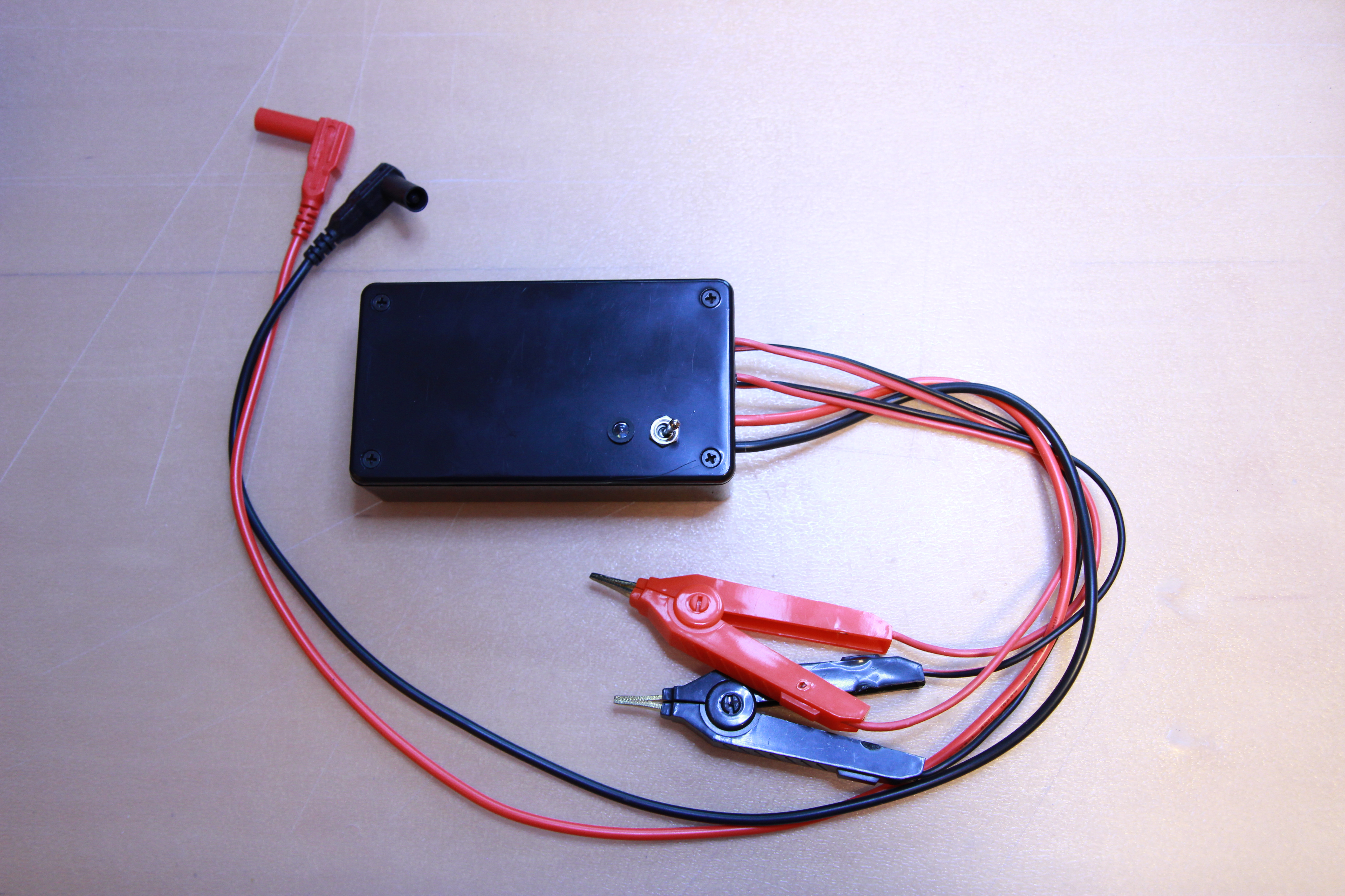
In the end, I decided to put it in a simple enclosure, use my DMM instead of a dedicated display. I'm not using it so often enough so that it warrants a dedicated display.
The 9V battery is a re-chargeable one.


The shielded DMM leads plug directly into my DMM.
I used my 6.5 digit DMM and was able to adjust the current to 100.002mA.
Testing a few reference value shunt resistors showed very precise measurements. My 6.5 digit DMM cannot measure this low and accurate by a long shot. However, it functions perfectly as a display for the instrument, showing the DC voltage that is representing the value of the resistor.
This is a very nice tool to have in your collection. Highly recommended!
If you like what you see, please support me by buying me a coffee: https://www.buymeacoffee.com/M9ouLVXBdw
No comments:
Post a Comment