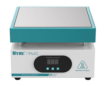
The UYUE 946C hotplate is a 600W 20x20cm device that can be set for a constant temperature by the user interface. There are many variations and versions available with the same model name and for very reasonable prices.
Initially, I wanted to build my own hotplate from scratch, by using a heater and design a controller for it. I even purchased a few different heaters and a thick aluminum plate.
However, after contemplating on how to put it all together, I was not happy or comfortable about the fact that this contraption would be lying on my desk, without a proper enclosure and also dealing with very hot surfaces, and controlling the mains voltage. So for about two years, I stashed the components away, and kept the project on the back-burner. I stayed on the look-out for a solution, but I discounted all oven-designs because they are too bulky for the precious amount of space I have in my man-cave/office. In the mean-time, I investigated a number of DIY controller designs that I liked.
A few months ago, I revisited a YouTube video of a hotplate design I liked earlier, but this time the Maker (Curious Scientist) upgraded it to a new version.
I particularly liked the way he shows the reflow curve, and he also shows the actual temperature over time. I was already planning to make my own electronics, so I contacted him for a copy of the Sketch which he gracefully did.
I also ordered the hotplate, but since I knew it would take some time to arrive, I built a prototype for the controller so I could run the software and see what I wanted to change for my version.
It took about 2 months for the hotplate to arrive, and in the mean-time I worked off-and-on on the code. At first learning how it worked, but also quickly changing or expanding it to my liking. That turned out to be a much more involving job than I anticipated. All in all, it's a big program with many lines of code (right now there are 2399 lines, but also many with comments)
Here are some of the changes I implemented that were different from the original design. First, I wanted to use an SSR unit, and not deal with my own circuit to control the heater. It would be much easier to keep all the mains related voltages and current far away from my controller.
I also wanted to use a faster processor, because the Arduino Nano that I initially used was too slow to my liking, even though I added hardware SPI to update the TFT much faster. After some time, I also changed the TFT display to a larger version, a 2.8' 240x320 display, based on the ILI9341 controller, and again used the hardware SPI interface to speed things up.
Next I wanted to improve on the rotary encoder code and make it more reliable. Initially, I used my own encoder, but later changed it to the same module that was used in the original version, because I discovered that it has some issues. Some of which was caused by the significantly faster processor, but I also noticed glitches and other issues. First off, the de-bounce capacitors on that module are too large with 100nS, creating a slope that the much faster ESP32 triggers on while in the "dead-zone" between logical levels. Here is what I mean:
The above was taken with a 10K pull-up, another 10K in series and than a 100nF debounce to GND, like it is on the Youmile? or KY-40? module. You can clearly see that there are multiple pulses around the point on the slope where a digital "0" is changing to a "1".
When you zoom in, you can see the real issue in more detail. Realize that every "glitch" is an interrupt to the processor. This is a little less important with slow processors, like the Nano, but a real issue with faster ones, like the ESP32.
So, the remedy is first to reduce the capacitor value to create a more adequate R/C with 10nF, and also use a Schmitt-trigger gate to bring that "slow" ramping signal back to a fast edge again, and feed that single pulse to the processor. It will be a lot happier.
Note that the above screen is taken with the 10K/10K/100nF values that is standard on these modules. Be aware!
The UYUA 946C Preheating Station
When the hotplate finally arrived, the first thing I did was to open it up before connecting it to the mains. There are numerous situations reported that whatever comes from China does not meet European safety specifications.
Unfortunately, my unit had the same issue others reported earlier, inadequate grounding of the metal parts to earth. There is no star-washer used anywhere, and at the contact point, the paint had not been removed. Also, the ground lead is a little on the thin side. I will be getting close to 10A, so this needs to be fixed.
That's easy to do though.
Here is a picture of the original controller that I was going to replace anyway.
The other, even more important question I had was what kind of heaters were installed. This was important for me, because I already figured out that 600W was probably not adequate, so I needed a way to add extra heater elements.
This actually looked very good. I was happy to see what I got. There are two round 8mm diameter rods of 350W each inserted in the aluminum profiles. The K-type sensor is bolted in between them, but on the edge.
First try
After adding another grounding lead from the thick aluminum plate to the bottom, and scraping paint and adding star washers on all connections from the bottom screws to the upper part, and putting it back together. I could try to see how it worked, and although a bit slow to heat-up, I was pretty pleased.
There was room for improvements.
Adding an additional heater element
The next step was to add another heater element. I already had one, so I cut the flanges off with a hack saw, so it would fit in-between the already installed elements.
The "extra" nuts you see where just about thick enough to use the original screws, but now also pressed the extra heater to the plate.
It worked, but this particular heater element self regulated the maximum temperature to 200 degrees C. When the temperature reached this level, it would stop contributing.
Adding insulation
To get some more mileage out of the heaters, I purchased insulation sheets with a self-adhesive back, and covered the insides of the top box of the enclosure.
First actual reflow on PCB's
Pretty pleased with this, I tried it out on two new boards I just received for my LORA-based mailbox notifier. It soldered pretty well, although I later found out that the reflow was not long or hot enough for the larger parts, but as a first trial, I was very happy.
At this moment, I was already convinced that this hotplate would only solder low-temperature solder pastes (138 degrees) well enough. Too bad, because I still have a lot of the 165 degree solder paste left, but I could always see what can be done after the units was operational the way I wanted it to be.
Addressing the ramp-up and maximum temperature
In order to address the rather slow heat ramp-up and maximum temperature challenge, I ordered two different kind of elements that would boost the power.
A failed attempt
These round 8mm heater elements are 250W each. I searched and searched for the right profile like the two already installed, but was unsuccessful. Wanting to try it out anyway, I concocted two strips that would hold the three elements in place, and pressed them to the top plate.
It worked, I had a lot more energy available, but when I opened the enclosure again to try the other new element, I got kind of scared.
Worse, one of the aluminum braces was completely burned through.
Wow, this is definitely not the way to go! I may revisit this when I can find the proper profiles to slide these elements into, but so far, I can't find them.
Next trial
Next up, I wanted to try the other heater element that I ordered.
This is a 220V 250 degree C 600W version.
I hoped that it would fit by drilling some extra holes so I could use the original screw holes, but by using longer screws and I mounted it upside down. I did not have the get the hacksaw out, it fitted perfectly.
The fit was just about perfect.
I also changed the K-type sensor to a new one that was more sturdy. To make that fit I had to add a slit into the new element.
I also had to move the tapped hole a little further to the edge. I used an M4 tap. Be careful not to drill too deep.
This is a result by using the "free" Heating mode set to 200 degrees. Most important is the ramp-up period to reach 200 degrees C. (note that the temperature scale is off, the curve is correct, and that has been fixed)
I used my IRmeter to have a look at the resulting temperature on a real PCB using the reflow profile of the Sn42/Bi57.6/Ag.04:
Note that the temperature colors look pretty dramatic, but are less than 7 degrees apart.
I did many, many more tests, mostly to refine the software and tune the ramp-up and overshoot issues, but I also tried out the hardware features. I was still contemplating to use two SSR's to drive the heaters, one for the boost phase, but so far, I have been able to address all of that in the software.
I also experimented quite a bit with two 12V 80x80mm fans to cool the hotplate down. Now that I know that it all works, I can finish the circuit and start to build a PCB.
The Controller
The final schematic that I'm going to work from looks like this:
It's actually quite simple, but has a few maybe not-so-obvious elements, so let me explain.
I'm going to use a rotary encoder that can be used from the outside of the enclosure. I did not want to use a module, because that is mechanically not very stable. That means that I created the debounce circuits on the main PCB. As I explained above, I'm using Schmitt trigger gates to clean-up the slower R/C slopes of the two critical signals, the ENC-CLK that triggers the interrupt, and ENC-BUT for the pressing of the button. This cannot be used in an interrupt due to the large amount of TFT activity, so this signal is polled. I could have used a Schmitt-trigger chip with two gates, but I don't have that one in stock.
The main power supply is quite simple. I'm using a 220V to 12V-1A power brick and connected that inside the enclosure. The output of that brick goes to the main PCB. The 12V is needed for the fans and is also regulated down to 5V that supplies the components on the main PCB.
Make sure that you connect the negative lead of the 12VDC also to earth ground of the enclosure. Not only is this safer, it will also remove possible mains related hum from the (extremely sensitive) K-Type sensor.
To the right of the supply is the transistor that I use to control the SSR-40 DA module. The input can be from 3-32VDC, and I'm supplying a PWM signal to regulate the output for the heaters. At first I contemplated using two heater sections and two SSR's, but I could control the heaters tied together in software to mainly avoid overshooting or regulating a constant temperature.
Below it is the circuit to drive the Waveshare 2.4" 240x320 pixel resolution TFT display. This display fits almost exactly in the square hole of the enclosure after I removed the original controller and face plate. The TFT uses the ILI9341 controller. In the software, I'm using the TFT_eSPI library because it's faster then the Adafruit version and allows some extra functionality. When the TFT display is powered-up, it shows a white display all the way up to initializing it. I don't like that, so I added a power on-off circuit that I can control in the code. Normally you would tie the reset signal of the TFT to the reset signal of the processor, but the ESP32 has no pin for that. I can control the reset by a port if needed after the power-up.
To the right of that circuit is the hardware that allows me to control a 12VDC fan, or two fans, like I use in parallel. I will have a DC jack on the enclosure to provide power to the fans.
In the middle is the circuit for the MAX6675 that reads the K-Type temperature sensor. During the prototyping phase, I used one of these modules that are easy to use for that purpose. I'm going to take the chip of that board and solder is on my main PCB.
To the far right is the circuit for the ESP32 with all the connections. The ESP will be socketed on the main board.
The 6 mounting holes below it are for the fastening of the TFT board to the main PCB, and also the main PCB to the enclosure, using the holes that are already there.
Obtaining the correct ESP32 variation
There are many, many variations of the ESP32 board. I'm using a version that is smaller in width and shorter in length. This is my preferred version of the ESP32, because it fits prototype boards. Most of the others are too wide and you have to connect two prototype boards next to each other to make the ESP board fit.
The version I'm using is called the ESP32 DEVKIT V1 from DOIT. There is also one that is virtually the same, called the ESP32 VROOM 4MB DEVKIT V1. If you Google for these names, you will most likely find them. However, there is more to watch out for.
This board only has 30 pins, and the pin rows are about 25mm apart, which is why it will fit in a single prototype board. To make absolutely sure you have the correct version, you also need to look at the available pins on the board. The most important thing to look for are the pins are either end of the board. They must match the picture below.
Even then, there could be two other issues that I describe in a section further below. The board above has the blocking diode installed, visible just below the voltage regulator.
The PCB Layout
The actual layout went pretty fast, although the challenge first was to get the mechanics right with the mounting of the TFT display to it would fit in the enclosure opening, the mounting of the studs to secure it, and the holes to secure the TFT to the PCB.
When I submitted the project to PCBWay for their approval and sponsoring on a Saturday, on Monday I got the go ahead and the funds were in my account. I submitted the final order on Tuesday and I received the boards that same Friday. Even DHL contributed positively this time by passing it through very rapidly without hold-ups at customs. Wow, from order to boards in hand in less than a week, that's impressive!
As usual, the boards have excellent quality. One of the tell-tale signs of quality is the centering of holes in the center of the pad, and they do that very, very well. Always dead center. Another tell tale sign is the crispness of the silkscreen, even with smaller fonts. One more tell tale sign is the plating of the (mounting) holes in the board. The insides are well plated and also connected to the outer ring. The hole positions and sizes are perfect.
In any case, I stuffed the PCB and reflow soldered it on the hotplate with the prototype controller. It went very well, there was only one suspicious soldering joint (too cold) and one solder blob between the pins of the tiniest part on the board. That was easily fixed. I was using the 14-bit MAX31855 instead of the MAX6675, but I found that the reported temperature is a little jittery, causing the reflow curve to be a lot less smooth. Just a bit of warning if you consider using this part. We don't need more than 12-bits, and the MX6675 is actually cheaper.
Bummer!
When I added the THT parts after the reflow soldering, I noticed a goof with the rather special mounting block for the K-Type sensor. I took that from the circuit board module that I had been using so far, together with the MAX6675 chip. I used the standard 5mm spacing for the layout, but this connector is larger. For the time being, I'm using a 5mm version, but I corrected the layout.
The rest of the mounting was pretty uneventful, although I did not mount the TFT screen yet. It will have to be soldered onto the board connector pins at the very last minute, because removing it later on is going to be a pain. There is no room for a socket or header.
After an inspection and a flux clean-up, I tested the various circuits by just using a DMM and my power supply, and verified the rails. I also tested the activation of the voltage regulator for the TFT, and that seems to work as well, but that was without the TFT connected.
Another bummer: a KiCad issue - watch out!
I added headers for the ESP32 DEVKIT1, but when I wanted to mount the board, it did not fit. I used the standard ESP32-C3-DevKitM-1 footprint, in the understanding it was the correct one. You should know that most ESP32 boards are wider than most others, like ESP8266 or Arduino Nano's. It's a real gotcha.
Well, it got me. I used the ESP32DEVKIT1 in another project without issues, so at first I didn't get it.
After some searching, I found the root cause. I recently upgraded KiCad to version 9, and I now noticed that my own footprints and symbols were not migrated and installed, although I said yes when asked for the migration for the previous version of KiCad during the installation.
Looking at the documentation in more detail (RTFM!), I now noticed that user libraries are not installed, you have to do that by hand. In my own footprint library, I have the correct version for the ESP32DEVKIT1, so the fix was easy, but I'm now left with a board that needs some surgery.
In any case, this is how it looks like:
The board is actually shown upside down, but you can see that the TFT is mounted on front of the PCB, together with the rotary decoder, facing the outside of the enclosure. The 8mm M4 mounting studs allow me to secure the board inside the window of the enclosure that becomes free when you remove the older stuff. The enclosure already has holes for the mounting, although I needed to drill them out to 3.5mm and counter-sinked (sunk?) them on the front.
This is the back of the PCB, facing the inside of the enclosure, where most of the parts are located. Top left is the replacement connector for the K-Type sensor. The TFT display is mounted using the studs and screws that it came with. I just added two screws to mount it on the PCB.
Please take note that the -12V input, or the wall-wart GND, also gets connected to the earth ground of the enclosure, which is securely connected to the earth ground of the 230V receptacle.
To the right are the headers for the ESP32, that are now too close together. A major goof.
I have ordered some more ESP32DEVKIT1 modules without the connector pins soldered, and I'm hoping I can bend the pins and the headers such that it will fit, otherwise I have to figure something else out, or order new boards. I already fixed the layout so we now have Version 2.1 although there are no schematic changes as yet. I hope I can brute force the ESP into the headers so I can give it all a try to make sure it works before I order new boards.
I tried a few things, but the board continued to pop out of the sockets. I finally created a set of extenders that allowed me to plug-in the ESP32 board and verify the rest of the controller. And then, I found another foot print error, this one for the 2N3904 transistor. There are SMD foot prints that swap the B and E connections, and yet, I picked the wrong one. I tested it by flipping the transistor upside down which would flip back the E and B leads. Then there was a filter capacitor that I placed not where it should be (close to a chip).
I fixed the four layout errors and ordered new boards that PCBWay gracefully sponsored again, despite my goofs. They arrived quickly so I could build-up a new board to give it another try. This time it seemed to work, but as soon as I turned the heater on, the screen went blank, the controller powered down and went through a reset. Oh bummer, now what?
I had been using this setup for several weeks now, and thoroughly tested it, I thought. After some tests, I found out that it was the 12VDC wall-wart that caused the problem. It is a very, very old 1Amp supply that I hadn't used in years, but it worked for several weeks without an issue. My take on it is that one or more capacitors inside the supply probably gave up on me, and just adding 50mA or so when the SSR was activated caused the supply to drop the voltage. Replacing it with a more modern and beefier unit fixed it all.
Here is how it looks now with everything installed and working.
I have not figured out yet what I'm going to do about the left and right side of the TFT. It's functional, but does not look that nice. Unfortunately, I don't have a 3-D printer (yet?) so it will have to be like that for a while, or I can figure out to create a small window-frame from mylar or something like that..
Here are pictures of the inside:
The black box in the background is the 12VDC wall-wart that powers the controller and the fans.
To the left is the SSR.
In the top right corner is the 12VDC chassis part that the fans plug in to. Make sure that this DC chassis part is isolated from the metal frame because the minus connection for the fan(s) is not earth-ground! If the minus of the Fans is at GND/EARTH level, the switching MOSFET is bridged/shorted and the fans will run at full speed and cannot be turned off by the controller. Feel free to use another connector for the fans, I used what I had in stock, with this caveat.
K-Type Thermocouple color coding
It is important to connect the proper K-Type thermocouple leads to the connector and hence the MAX6675 inputs. There is a positive and a negative input. The color coding for these thermocouples is rather strange, but this
table explains it all. According to this table, I have the German DIN13711 color coding because the wires from my K-Type are Green and Red. So according to this table, Red is positive and Green is negative.
The MAX6675 blew itself(?) up
When I was using the reflow oven, it suddenly developed an issue with the temperature reading. It turned out that the MAX6675 developed an internal short between a thermocouple lead and VCC. When I investigated this, I saw that the MAX6675 reported a status error 4, indication just that, a short. The result was that the temperature reading was 1024 degrees, obviously this is the maximum possible reading with a 12-bit ADC.
Replacing the chip solved the issue, but I also found out that I probably made a mistake that could have contributed to the demise of the chip. According to the datasheet, you should connect the minus lead of the thermocouple to circuit GND. I did not do that, under the impression that the floating input with the braided and grounded cover would take care of that. Apparently not, so I stand corrected. The fix is easy, just connect the minus lead of the thermocouple to circuit GND by soldering a short wire from the connector pin to the ground plane.
ESP32 Board Caveat
When I was researching the defective MAX6675 issue, I also stumbled into another trap that I already knew but overlooked, the ESP32 board caveat. There is a potential problem with some of the ESP32 boards that may bite you. If you are familiar with these Arduino and ESP boards, you will know that there is normally a blocking diode on the board that prevents back-feeding the 5V through the USB connector to your PC. However, on some of the ESP32 boards, this diode is missing, and the manufacturer installed a 0 Ohm resistor instead.
This is not an issue when you feed the 5V from the USB port to the ESP32 board, but if you power the ESP32 board from a voltage from your board, you will send a current of several hundred mA to your PC. Not only is this an unhealthy situation for your PC, but also the voltage regulator on your board may not be able to sink that much extra current.
During the design phase, I used an ESP32 board that had the diode in place, there is a picture of it further up, so there was no issue. However, I decided to use another ESP32 board in the final version with the corrected PCB layout, which was OK, because I didn't need a USB connection when operating the reflow controller.
The picture above shows the rather interesting way of soldering the reset capacitor to the EN button on the left. What is more to the point, in the middle is the blue arrow pointing to the 0 Ohm resistor that should have been a 5V blocking diode.
So, when I found out that the MAX6675 was showing problems, I was debugging this with the USB port connected, so I could use serial monitor to see what was going on. That was working fine, until I burned my finger on the 5V regulator. I quickly realized what the problem was, and remembered the root cause that I already found when designing the Dynamic DC load that has the same issue.
There are a few remedies:
- Do not use the USB connection when you power the ESP from the controller board.
- Remove the 0402 0 Ohm resistor from the ESP32 board. However, that will prevent you from powering the ESP32 solely from the USB port. You could add a 0402 Schottky diode in place of the 0402 resistor, but that's tricky if you use a heat gun.
- Install the blocking diode on the controller board by cutting the 5V supply trace and install the diode there. (Cathode towards the ESP32)
Redesign of the PCB to V2.2
Because of the two above mentioned issues, I made a few corrections to the schematic and redid the layout to accommodate the grounding of the thermocouple lead, and I also added improved grounding for the MAX6675 as well.
Second, I also added the possibility to either install a 0 Ohm resistor in the 5V path to the ESP32 if your ESP32 board already has the blocking diode, or install the blocking diode on the controller board if your ESP32 board does not have it.
The Github site and the PCBWay Shared Project now have the V2.2 layout.
In the meantime, I did solder a rather large (123x83mm) and pretty complex PCB with many parts. large and small for new project, and that worked well. So with the latest changes to the controller, I'm happy to have this additional tool. It's a huge time saver compared to a heat gun, and it's also much easier for soldering larger components like large size Tantalum capacitors.
Using fans
I looked at integrating the fans into the enclosure, but things get too hot, and the effectiveness would not be great anyway.
If your going to use the optional fans, have a look at the pictures below to see what I concocted instead during the prototyping phase. This actually worked so well that I kept it that way. The fans are 12V 80x80mm, and I used an aluminum strip to mount them side by side. I then used one of those cheap flexible circuit board holders to position them such that they blow across the surface. The 12V power wires are soldered to a 12V plug in parallel.
Warnings!
The code that I wrote only works with Visual Studio Code (VSC), and NOT with the Arduino IDE. The reason for this discrepancy is the difference in libraries for the display and the way you need to address the SPI bus ports. There have been a few makers that built the hotplate, but ran into issues with the display. It stayed blank. They used the Arduino IDE.
It has been pointed out that I connect the MAX K-type convertor to 5V, while the ESP32 is a 3V3 device. This is no problem for the CS and SCK signals because they are generated by the ESP and the MAX can easily handle these voltages. The SO signal is an output from the MAX and goes to a 3V3 level input of the ESP. The internal (ESD) protection diodes for the ports will normally take care of this.
According to the above datasheet, the SO output has a drive capability of only 1.6mA. This is low enough for a short burst for the ESP32 inputs, and should pose no problem.
If you are concerned about this, there are three remedies that you can apply to the current PCB. You can cut the SO trace and add a 1K series resistor lowering the current some more. You can add a (Schottky) diode with the Anode connected to the SO pin of the ESP32, and the Cathode to the 3V3 output pin 16. This will clamp the SO voltage to the 3V3 level, and will help the internal clamping diode of the port, that has a lower capacity.
The last remedy is to cut the 5V VCC trace to the MAX chip and use a small patch wire to connect it to the plus of C12, the 3V3 supply. I have not verified any of these changes.
When I decide to do a new board turn, I will consider making the VCC change, but need to verify the proper operation before I will publish this change.
Github repository
I have created a Github repository with all the design information. It can be found
here.
There is also a shared project on the PCBWay site so if you want to order PCB's, populated or not, you can go there.
I may be adding information for a while while I'm collecting data from reflow soldering actual boards, so stay tuned! Keep in mind that you may have to tune the software to adopt the reflow profile to the actual results. Your heating elements -will- be different from those that I'm using.