Show by Label

Thursday, February 20, 2025

Creating a Hotplate Reflow Station


This project describes how I converted a UYUE 946C Preheating Station to a reflow hotplate that uses and follows solder paste profiles.


As I normally do on my Blogs, I describe the way I get to the final design, with trials and errors, ups and downs, warts and all, but hopefully in a way that you learn something, and avoid my mistakes. With my projects, it's not going to be an IKEA type quickly-build-it-design. Some effort is required.

Overview

The UYUE 946C hotplate is a 600W 20x20cm device that can be set for a constant temperature by the user interface. There are many variations and versions available with the same model name and for very reasonable prices.

Initially, I wanted to build my own hotplate from scratch, by using a heater and design a controller for it. I even purchased a few different heaters and a thick aluminum plate.

However, after contemplating on how to put it all together, I was not happy or comfortable about the fact that this contraption would be lying on my desk, without a proper enclosure and also dealing with very hot surfaces, and controlling the mains voltage. So for about two years, I stashed the components away, and kept the project on the back-burner. I stayed on the look-out for a solution, but I discounted all oven-designs because they are too bulky for the precious amount of space I have in my man-cave/office. In the mean-time, I investigated a number of DIY controller designs that I liked.

A few months ago, I revisited a YouTube video of a hotplate design I liked earlier, but this time the Maker (Curious Scientist) upgraded it to a new version.

Here is that video: YouTube

I particularly liked the way he shows the reflow curve, and he also shows the actual temperature over time. I was already planning to make my own electronics, so I contacted him for a copy of the Sketch which he gracefully did.

I also ordered the hotplate, but since I knew it would take some time to arrive, I built a prototype for the controller so I could run the software and see what I wanted to change for my version. 


Above is the prototype with the Nano, the original 1.8' 128x160 TFT display, my own rotary encoder with the debounce components and the MAX6675K module to read the K-Type sensor that you also see in the picture.

It took about 2 months for the hotplate to arrive, and in the mean-time I worked off-and-on on the code. At first learning how it worked, but also quickly changing or expanding it to my liking. That turned out to be a much more involving job than I anticipated. All in all, it's a big program with many lines of code (right now there are 2399 lines, but also many with comments)

Changes to the hardware and the code

Here are some of the changes I implemented that were different from the original design. First, I wanted to use an SSR unit, and not deal with my own circuit to control the heater. It would be much easier to keep all the mains related voltages and current far away from my controller.

I also wanted to use a faster processor, because the Arduino Nano that I initially used was too slow to my liking, even though I added hardware SPI to update the TFT much faster. After some time, I also changed the TFT display to a larger version, a 2.8' 240x320 display, based on the ILI9341 controller, and again used the hardware SPI interface to speed things up.

Next I wanted to improve on the rotary encoder code and make it more reliable. Initially, I used my own encoder, but later changed it to the same module that was used in the original version, because I discovered that it has some issues. Some of which was caused by the significantly faster processor, but I also noticed glitches and other issues. First off, the de-bounce capacitors on that module are too large with 100nS, creating a slope that the much faster ESP32 triggers on while in the "dead-zone" between logical levels. Here is what I mean:


The above was taken with a 10K pull-up, another 10K in series and than a 100nF debounce to GND, like it is on the Youmile? or KY-40? module. You can clearly see that there are multiple pulses around the point on the slope where a digital "0" is changing to a "1".


When you zoom in, you can see the real issue in more detail. Realize that every "glitch" is an interrupt to the processor. This is a little less important with slow processors, like the Nano, but a real issue with faster ones, like the ESP32.

So, the remedy is first to reduce the capacitor value to create a more adequate R/C with 10nF, and also use a Schmitt-trigger gate to bring that "slow" ramping signal back to a fast edge again, and feed that single pulse to the processor. It will be a lot happier. 


Note that the above screen is taken with the 10K/10K/100nF values that is standard on these modules. Be aware!


The UYUA 946C Preheating Station

When the hotplate finally arrived, the first thing I did was to open it up before connecting it to the mains. There are numerous situations reported that whatever comes from China does not meet European safety specifications. 


Unfortunately, my unit had the same issue others reported earlier, inadequate grounding of the metal parts to earth. There is no star-washer used anywhere, and at the contact point, the paint had not been removed. Also, the ground lead is a little on the thin side. I will be getting close to 10A, so this needs to be fixed.

That's easy to do though.


Here is a picture of the original controller that I was going to replace anyway.


The other, even more important question I had was what kind of heaters were installed. This was important for me, because I already figured out that 600W was probably not adequate, so I needed a way to add extra heater elements.


This actually looked very good. I was happy to see what I got. There are two round 8mm diameter rods of 350W each inserted in the aluminum profiles. The K-type sensor is bolted in between them, but on the edge. 


First try

After adding another grounding lead from the thick aluminum plate to the bottom, and scraping paint and adding star washers on all connections from the bottom screws to the upper part, and putting it back together.  I could try to see how it worked, and although a bit slow to heat-up, I was pretty pleased.

There was room for improvements.


Adding an additional heater element

The next step was to add another heater element. I already had one, so I cut the flanges off with a hack saw, so it would fit in-between the already installed elements.


The "extra" nuts you see where just about thick enough to use the original screws, but now also pressed the extra heater to the plate.

It worked, but this particular heater element self regulated the maximum temperature to 200 degrees C. When the temperature reached this level, it would stop contributing. 


Adding insulation

To get some more mileage out of the heaters, I purchased insulation sheets with a self-adhesive back, and covered the insides of the top box of the enclosure.


First actual reflow on PCB's

Pretty pleased with this, I tried it out on two new boards I just received for my LORA-based mailbox notifier. It soldered pretty well, although I later found out that the reflow was not long or hot enough for the larger parts, but as a first trial, I was very happy.

At this moment, I was already convinced that this hotplate would only solder low-temperature solder pastes (138 degrees) well enough. Too bad, because I still have a lot of the 165 degree solder paste left, but I could always see what can be done after the units was operational the way I wanted it to be.


Addressing the ramp-up and maximum temperature

In order to address the rather slow heat ramp-up and maximum temperature challenge, I ordered two different kind of elements that would boost the power.


A failed attempt

These round 8mm heater elements are 250W each. I searched and searched for the right profile like the two already installed, but was unsuccessful. Wanting to try it out anyway, I concocted two strips that would hold the three elements in place, and pressed them to the top plate.


It worked, I had a lot more energy available, but when I opened the enclosure again to try the other new element, I got kind of scared.


Worse, one of the aluminum braces was completely burned through.


Wow, this is definitely not the way to go! I may revisit this when I can find the proper profiles to slide these elements into, but so far, I can't find them.


Next trial

Next up, I wanted to try the other heater element that I ordered.

This is a 220V 250 degree C 600W version.

I hoped that it would fit by drilling some extra holes so I could use the original screw holes, but by using longer screws and I mounted it upside down. I did not have the get the hacksaw out, it fitted perfectly.


The fit was just about perfect.


I also changed the K-type sensor to a new one that was more sturdy. To make that fit I had to add a slit into the new element.
I also had to move the tapped hole a little further to the edge. I used an M4 tap. Be careful not to drill too deep.

This is a result by using the "free" Heating mode set to 200 degrees. Most important is the ramp-up period to reach 200 degrees C. (note that the temperature scale is off, the curve is correct, and that has been fixed)


I used my IRmeter to have a look at the resulting temperature on a real PCB using the reflow profile of the Sn42/Bi57.6/Ag.04:


Note that the temperature colors look pretty dramatic, but are less than 7 degrees apart.

I did many, many more tests, mostly to refine the software and tune the ramp-up and overshoot issues, but I also tried out the hardware features. I was still contemplating to use two SSR's to drive the heaters, one for the boost phase, but so far, I have been able to address all of that in the software. 

I also experimented quite a bit with two 12V 80x80mm fans to cool the hotplate down. Now that I know that it all works, I can finish the circuit and start to build a PCB.


The Controller

The final schematic that I'm going to work from looks like this:


It's actually quite simple, but has a few maybe not-so-obvious elements, so let me explain.
I'm going to use a rotary encoder that can be used from the outside of the enclosure. I did not want to use a module, because that is mechanically not very stable. That means that I created the debounce circuits on the main PCB. As I explained above, I'm using Schmitt trigger gates to clean-up the slower R/C slopes of the two critical signals, the ENC-CLK that triggers the interrupt, and ENC-BUT for the pressing of the button. This cannot be used in an interrupt due to the large amount of TFT activity, so this signal is polled. I could have used a Schmitt-trigger chip with two gates, but I don't have that one in stock.

The main power supply is quite simple. I'm using a 220V to 12V-1A power brick and connected that inside the enclosure. The output of that brick goes to the main PCB. The 12V is needed for the fans and is also regulated down to 5V that supplies the components on the main PCB. 

Make sure that you connect the negative lead of the 12VDC also to earth ground of the enclosure. Not only is this safer, it will also remove possible mains related hum from the (extremely sensitive) K-Type sensor.

To the right of the supply is the transistor that I use to control the SSR-40 DA module. The input can be from 3-32VDC, and I'm supplying a PWM signal to regulate the output for the heaters. At first I contemplated using two heater sections and two SSR's, but I could control the heaters tied together in software to mainly avoid overshooting or regulating a constant temperature.

Below it is the circuit to drive the Waveshare 2.4" 240x320 pixel resolution TFT display. This display fits almost exactly in the square hole of the enclosure after I removed the original controller and face plate. The TFT uses the ILI9341 controller. In the software, I'm using the TFT_eSPI library because it's faster then the Adafruit version and allows some extra functionality. When the TFT display is powered-up, it shows a white display all the way up to initializing it. I don't like that, so I added a power on-off circuit that I can control in the code. Normally you would tie the reset signal of the TFT to the reset signal of the processor, but the ESP32 has no pin for that. I can control the reset by a port if needed after the power-up.

To the right of that circuit is the hardware that allows me to control a 12VDC fan, or two fans, like I use in parallel. I will have a DC jack on the enclosure to provide power to the fans.

In the middle is the circuit for the MAX6675 that reads the K-Type temperature sensor. During the prototyping phase, I used one of these modules that are easy to use for that purpose. I'm going to take the chip of that board and solder is on my main PCB.

To the far right is the circuit for the ESP32 with all the connections. The ESP will be socketed on the main board.

The 6 mounting holes below it are for the fastening of the TFT board to the main PCB, and also the main PCB to the enclosure, using the holes that are already there.

The PCB Layout

The actual layout went pretty fast, although the challenge first was to get the mechanics right with the mounting of the TFT display to it would fit in the enclosure opening, the mounting of the studs to secure it, and the holes to secure the TFT to the PCB.

When I submitted the project to PCBWay for their approval and sponsoring on a Saturday, on Monday I got the go ahead and the funds were in my account. I submitted the final order on Tuesday and I received the boards that same Friday. Even DHL contributed positively this time by passing it through very rapidly without hold-ups at customs. Wow, from order to boards in hand in less than a week, that's impressive!

As usual, the boards have excellent quality. One of the tell-tale signs of quality is the centering of holes in the center of the pad, and they do that very, very well. Always dead center. Another tell tale sign is the crispness of the silkscreen, even with smaller fonts. One more tell tale sign is the plating of the (mounting) holes in the board. The insides are well plated and also connected to the outer ring. The hole positions and sizes are perfect.

In any case, I stuffed the PCB and reflow soldered it on the hotplate with the prototype controller. It went very well, there was only one suspicious soldering joint (too cold) and one solder blob between the pins of the tiniest part on the board. That was easily fixed. I was using the 14-bit MAX31855 instead of the MAX6675, but I found that the reported temperature is a little jittery, causing the reflow curve to be a lot less smooth. Just a bit of warning if you consider using this part. We don't need more than 12-bits, and the MX6675 is actually cheaper.


Bummer!
When I added the THT parts after the reflow soldering, I noticed a goof with the rather special mounting block for the K-Type sensor. I took that from the circuit board module that I had been using so far, together with the MAX6675 chip. I used the standard 5mm spacing for the layout, but this connector is larger. For the time being, I'm using a 5mm version, but I corrected the layout.

The rest of the mounting was pretty uneventful, although I did not mount the TFT screen yet. It will have to be soldered onto the board connector pins at the very last minute, because removing it later on is going to be a pain. There is no room for a socket or header.

After an inspection and a flux clean-up, I tested the various circuits by just using a DMM and my power supply, and verified the rails. I also tested the activation of the voltage regulator for the TFT, and that seems to work as well, but that was without the TFT connected.

Another bummer: a KiCad issue - watch out!

I added headers for the ESP32 DEVKIT1, but when I wanted to mount the board, it did not fit. I used the standard ESP32-C3-DevKitM-1 footprint, in the understanding it was the correct one. You should know that most ESP32 boards are wider than most others, like ESP8266 or Arduino Nano's. It's a real gotcha.
Well, it got me. I used the ESP32DEVKIT1 in another project without issues, so at first I didn't get it. 

After some searching, I found the root cause. I recently upgraded KiCad to version 9, and I now noticed that my own footprints and symbols were not migrated and installed, although I said yes when asked for the migration for the previous version of KiCad during the installation.

Looking at the documentation in more detail (RTFM!), I now noticed that user libraries are not installed, you have to do that by hand. In my own footprint library, I have the correct version for the ESP32DEVKIT1, so the fix was easy, but I'm now left with a board that needs some surgery.

In any case, this is how it looks like:


The board is actually shown upside down, but you can see that the TFT is mounted on front of the PCB, together with the rotary decoder, facing the outside of the enclosure. The 8mm M4 mounting studs allow me to secure the board inside the window of the enclosure that becomes free when you remove the older stuff. The enclosure already has holes for the mounting, although I needed to drill them out to 3.5mm and counter-sinked (sunk?) them on the front.


This is the back of the PCB, facing the inside of the enclosure, where most of the parts are located. Top left is the replacement connector for the K-Type sensor. The TFT display is mounted using the studs and screws that it came with. I just added two screws to mount it on the PCB.

Please take note that the -12V input, or the wall-wart GND, also gets connected to the earth ground of the enclosure, which is securely connected to the earth ground of the 230V receptacle. 

To the right are the headers for the ESP32, that are now too close together. A major goof. 


I have ordered some more ESP32DEVKIT1 modules without the connector pins soldered, and I'm hoping I can bend the pins and the headers such that it will fit, otherwise I have to figure something else out, or order new boards. I already fixed the layout so we now have Version 2.1 although there are no schematic changes as yet. I hope I can brute force the ESP into the headers so I can give it all a try to make sure it works before I order new boards.

I tried a few things, but the board continued to pop out of the sockets. I finally created a set of extenders that allowed me to plug-in the ESP32 board and verify the rest of the controller. And then, I found another foot print error, this one for the 2N3904 transistor. There are SMD foot prints that swap the B and E connections, and yet, I picked the wrong one. I tested it by flipping the transistor upside down which would flip back the E and B leads. Then there was a filter capacitor that I placed not where it should be (close to a chip). 

I fixed the four layout errors and ordered new boards that PCBWay gracefully sponsored again, despite my goofs. They arrived quickly so I could build-up a new board to give it another try. This time it seemed to work, but as soon as I turned the heater on, the screen went blank, the controller powered down and went through a reset. Oh bummer, now what? 

I had been using this setup for several weeks now, and thoroughly tested it, I thought. After some tests, I found out that it was the 12VDC wall-wart that caused the problem. It is a very, very old 1Amp supply that I hadn't used in years, but it worked for several weeks without an issue. My take on it is that one or more capacitors inside the supply probably gave up on me, and just adding 50mA or so when the SSR was activated caused the supply to drop the voltage. Replacing it with a more modern and beefier unit fixed it all.

Here is how it looks now with everything installed and working.


I have not figured out yet what I'm going to do about the left and right side of the TFT. It's functional, but does not look that nice. Unfortunately, I don't have a 3-D printer (yet?) so it will have to be like that for a while, or I can figure out to create a small window-frame from mylar or something like that..

Here are pictures of the inside:


The black box in the background is the 12VDC wall-wart that powers the controller and the fans.
To the left is the SSR.

In the top right corner is the 12VDC chassis part that the fans plug in to. Make sure that this DC chassis part is isolated from the metal frame because the minus connection for the fan(s) is not earth-ground! If the minus of the Fans is at GND/EARTH level, the switching MOSFET is bridged/shorted and the fans will run at full speed and cannot be turned off by the controller. Feel free to use another connector for the fans, I used what I had in stock, with this caveat.


K-Type Thermocouple color coding

It is important to connect the proper K-Type thermocouple leads to the connector and hence the MAX6675 inputs. There is a positive and a negative input. The color coding for these thermocouples is rather strange, but this table explains it all. According to this table, I have the German DIN13711 color coding because the wires from my K-Type are Green and Red. So according to this table, Red is positive and Green is negative.


The MAX6675 blew itself(?) up

When I was using the reflow oven, it suddenly developed an issue with the temperature reading. It turned out that the MAX6675 developed an internal short between a thermocouple lead and VCC. When I investigated this, I saw that the MAX6675 reported a status error 4, indication just that, a short. The result was that the temperature reading was 1024 degrees, obviously this is the maximum possible reading with a 12-bit ADC.

Replacing the chip solved the issue, but I also found out that I probably made a mistake that could have contributed to the demise of the chip. According to the datasheet, you should connect the minus lead of the thermocouple to circuit GND. I did not do that, under the impression that the floating input with the braided and grounded cover would take care of that. Apparently not, so I stand corrected. The fix is easy, just connect the minus lead of the thermocouple to circuit GND by soldering a short wire from the connector pin to the ground plane.


ESP32 Board Caveat

Ehen I was researching the defective MAX6675 issue, I also stumbled into another trap that I already knew but overlooked, the ESP32 bord caveat. There is a potential problem with some of the ESP32 boards that may bite you. If you are familiar with these Arduino and ESP boards, you will know that there is normally a blocking diode on the board that prevents back-feeding the 5V through the USB connector to your PC. However, on some of the ESP32 boards, this diode is missing, and the manufacturer installed a 0 Ohm resistor instead.

This is not an issue when you feed the 5V from the USB port to the ESP32 board, but if you power the ESP32 board from a voltage from your board, you will send a current of several hundred mA to your PC. Not only is this an unhealthy situation for your PC, but also the voltage regulator on your board may not be able to sink that much extra current.

During the design phase, I used an ESP32 board that had the diode in place, so there was no issue. However, I decided to use another ESP32 board in the final version with the corrected PCB layout, which was OK, because I didn't need a USB connection when operating the reflow controller.


The picture above shows the rather interesting way of soldering the reset capacitor to the EN button on the left. What is more to the point, in the middle is the blue arrow pointing to the 0 Ohm resistor that should have been a 5V blocking diode.

So, when I found out that the MAX6675 was showing problems, I was debugging this with the USB port connected, so I could use serial monitor to see what was going on. That was working fine, until I burned my finger on the 5V regulator. I quickly realized what the problem was, and remembered the root cause that I already found when designing the Dynamic DC load that has the same issue.

There are a few remedies:
  • Do not use the USB connection when you power the ESP from the controller board.
  • Remove the 0402 0 Ohm resistor from the ESP32 board. However, that will prevent you from powering the ESP32 solely from the USB port. You could add a 0402 Schottky diode in place of the 0402 resistor, but that's tricky if you use a heat gun.
  • Install the blocking diode on the controller board by cutting the 5V supply trace and install the diode there. (Cathode towards the ESP32)

Redesign of the PCB to V2.2

Because of the two above mentioned issues, I made a few corrections to the schematic and redid the layout to accommodate the grounding of the thermocouple lead, and I also added improved grounding for the MAX6675 as well.

Second, I also added the possibility to either install a 0 Ohm resistor in the 5V path to the ESP32 if your ESP32 board already has the blocking diode, or install the blocking diode on the controller board if your ESP32 board does not have it.

The Github site and the PCBWay Shared Project now have the V2.2 layout.


In the meantime, I did solder a rather large (123x83mm) and pretty complex PCB with many parts. large and small for new project, and that worked well. So with the latest changes to the controller, I'm happy to have this additional tool. It's a huge time saver compared to a heat gun, and it's also much easier for soldering larger components like large size Tantalum capacitors.

I have now created a Github repository with all the design information. It can be found here.
There is also a shared project on the PCBWay site so if you want to order PCB's, populated or not, you can go there


I may be adding information for a while while I'm collecting data from reflow soldering actual boards, so stay tuned!


Thursday, December 19, 2024

LoRa Mail Letterbox Notification


For quite some time, my wife had asked me to "produce something useful" instead of the projects I have been busy spending time and money on.

We live in an apartment building on the 3rd floor (4 for Americans) and our mailbox is next to the entrance together with the other 39 inhabitants. It's a full metal construction with an aluminum lid.

The distance is far exceeding a WiFi connection, so a LoRa connection should solve the distance issue.

Proof of Concept

I experimented with two of the E32 433MHz boards and quickly got that up and running using Arduino Nano boards, with two simple sketches. One acting as the sender and one acting as the receiver with an acknowledgement going back to the sender to turn on an LED. Powering the sender one with a Powerbrick, I ventured a few times up and down the stairs to the mailbox to see if I could get a reliable connection from within the metal enclosure, which I did.

Extending the Proof of Concept

In order to make this more reliable and practical, I wanted to put the sender contraption into deep sleep to conserve power, and waking it up somehow when mail got delivered.

I first tried to use an LDR that would function as a wake-up for the system. Unfortunately, my first attempts failed. I think this is because the mailbox itself it dark, and opening the lid and shoving mail through the opening did not provide enough of a light differential to use it as the trigger. This is unreliable because the postman or woman stands in front of the mailbox, blocking light and that in the winter period is another obstacle.

Besides, the circuit to recognize the opening of the lid by means of an LDR would have to be powered 24x7 and that would drain the battery cell.

It would have been nice nonetheless, because all the parts could be in one enclosure.

Alas, I had to find a different method, preferably one that did not use any power but would be reliable. So, the next thing I wanted to try was to use a magnetic reed switch, typically used for signaling doors opening. I ordered one, but it turned out to be too bulky for this application. The magnet piece would have to be connected to the lid by either glue or double sided tape because I can't drill holes anywhere. This bulky magnet part would be exposed to the outside when the lid opens, and it's too easy to get nocked off with bulky packages.

The next step was to try a smaller motion activated switch by a mercury droplet, which I found after some searching on Aliexpress. I knew about the existence, but looked for a really tiny one.


The glass bulb is 11mm long and has a diameter of only 4mm.

Using a different lid opening sensor

I have been notified by a viewer of this Blog that the mercury sensor I'm using can break the glass and the very toxic Mercury can leak out. He mentioned an alternative solution by using a vibration sensor. 

Vibration sensor

I didn't know about them so I ordered a few and will try them out. I ordered the normal sensitivity one and also the sensitive version.

This is how they look on the inside: (I borrowed the picture below from Adafruit: https://www.adafruit.com/product/2384


I got the vibration sensor with the normal sensitivity, the SW18020P and it is not really working well in this application. It needs quite a violent jolt to make contact, making it unreliable for the detection of the lid opening and closing. Maybe the more sensitive one works better?

I got the sensitive version, the SW18010P and tried that out. It indeed works a lot better, have a look:


It produces a large number of these very fast pulses when you tilt it or tap it. For this project, that would still work, but it seems not any more reliable or different enough to change it for the other vibration sensor. Al lot depends on the motion the lid will produce when it falls back down from opening it. It's also very appropriate for a door or window sensor, registering a break-in attempt as an example.


Optical light sensor

I also got delivery of another optical sensor, the OPT101. Using a sensor that does not have to be fixed to the lid is a major improvement, because everything can then be built in one box, and there are no wires going to the sensor mounted on the lid.

I built a little prototype with it, and initially, it seemed to work very well, just waving my hand above it would activate it. However, when I put it in the carton shoebox that would mimic the letterbox, I did not get enough light on the sensor to make it work. It's not sensitive enough for this application, even though I increased the gain.


Optical PIR sensor

I also ordered a small IR motion detector, I saw it was used in a mailbox alarm project where the designer sold his result. It uses one of these small sensors.

When I tried it, it worked very well, even within the concocted shoebox replacement, but as I already feared, it only reacts on Infra-Red generated from warm bodies. In other words, it will only work when the postman puts a bare hand for the opening, but it does not react on any light. This will be a very unreliable detector for my particular mailbox. It may be better suited for the US mailboxes that have a much larger opening. I had high hopes for this sensor, but alas...


Tilt switch

The tilt switch I also found while searching for alternatives is so far the best replacement for the mercury switch I'm currently using. As you can see in the picture that I borrowed from Adafuit (https://learn.adafruit.com/tilt-sensor/overview), it uses two balls that roll around and make contact when the device is up-right. Same as the mercury switch.


The ones I ordered arrived and seem to work fine. 


Changing the processor

I had a few issues with putting the Nano to sleep, and waking it up. Also these boards are a tad too large to my liking as well, so I switched to the ESP8266 based WEMOS D1 boards. I use a number of them in my home, measuring many environmental "things" and I always have a number in spare to play with. They have enough available pins to interface to the LoRa board and they can be put into a deep sleep mode with one instruction, while they wake-up when the RST pin is momentarily pulled low.

I'm using a clone of the WEMOS D1 Mini, the GY-D1MINI. The major difference is that it uses a SCP2104 USB to UART bridge, instead of the CH340C, which calls for another USB driver on your PC.

Unfortunately, although there are many variations and models, I have not been able to find a schematic for this particular board.


The proof of concept prototype

To try out the concept, I put together the following circuit diagram, build that on protoboard, mounted it into a small plastic enclosure and mounted the contraption with double sided tape inside the letterbox.


To keep an eye on the Lipo cell voltage, I use the on-board ADC to measure the cell voltage. I used a 120K resistor that works together with the on-board attenuator to keep the voltage within the ADC range. 

To get a more reliable communication, the sender sends a text message that it has detected mail. This message gets verified by the receiver after it than sends an acknowledgement. The sender waits for the acknowledgement, but if not received after a short period, it sends the "I got mail" message again, up to 5 times. After receiving the acknowledgement from the receiver, it would also measure and send the cell voltage to the receiver. On the receiver side, I use an LED to signal a low voltage, set at 3.4V. Reading the cell voltage just after activating the LoRa board, which uses about 100mA while transmitting, ensures that the cell is at the lowest level when I measure it, although the voltage will creep back up a bit when the circuit is put to sleep again.

This worked really well until I did not get any alarms anymore. It turned out that the so called 500mAh Lipo cell drained before mail arrived so I did not get the low battery warning. Bummer! At that time, I set the cell voltage warning at 3.4V, but later I figured out that this was way too low. Due to the voltage drop over the 3V3 regulator, an ME6211 with 260mV dropout, it very well could have resulted in a voltage for the ESP8266 and the LoRa board that was below 3V, at which level they stop working reliably or at all.

First of all, the 500mAh cell capacity was inadequate to begin with, but it is what I had. I had measured the two cells I have several years ago and they showed to have a capacity of only 274mAh and 260mAh.

Because I used the on-board 3V3 regulator  on the WEMOS D1 mini, by the time the cell produced less than 4V, the 3V3 voltage regulator started to drop the voltage, so I did not get much of a useful capacity to start with. I knew that, so I ordered two new LiPo cells with 2000mAh capacity. When they arrived I put one into the letterbox.

Here is a discharging curve for the 2000mAh LiPo cells I'm now using:


This graph was generated by my DC Dynamic Load in the Battery Test mode. That recent design is described elsewhere on my Blog. It shows a couple of things. First of all the discharge curve was made with a constant 200mA (1/10th) of the rated 2000mAh for the cell. The measurement shows that it's not quite up to the specification at 1889mAh, but close enough. It took 9 1/2 hrs to discharge it from fully charged to the 3.0V cutoff setting. The sender circuit should draw about 20uA when in deep sleep, and about 100-150mA when the LoRa module is transmitting for a few seconds. 

When you look at the discharge curve, you see some hash that goes away after 210 minutes. This is only the second time I'm discharging the cell, and from other tests, I'm assuming that the hash can be attributed to the chemical reaction within the cell. This is why I use a 220uF capacitor to smoothen that.

More about the cell voltage later on.

I installed the prototype board into a small enclosure and taped it to the inside of the letterbox with double sided foam tape and used two thin wires that went to the mercury switch that I taped to the lid. I also mounted a small connector to be used for the LiPo cell such that I can replace it without opening the enclosure. The cell is also taped to the side of the letterbox.

This prototype is working really well for a few weeks now. They major issue is that normally, I do not get a lot of mail. There may be days without any. The cell voltage only gets send to the receiver when there is mail, so there is too much of an opportunity that the cell gets depleted before I get mail and I'm unaware of this. I need to find a way to avoid that.


The receiver

The receiver basically has the same ESP8266 and LoRa module, but the circuit is enhanced to give audible and visual information. The receiver is located in the apartment where we can hear it beep, see the LED's and reset the alarm.


This circuit is powered by a 5V USB wall wart connected to the WEMOS D1 mini micro USB input connector. There is a beeper/buzzer that will activate when mail is received and it will beep 5 times. An LED is turned on so you also have a visual indication that mail is received.

You can reset the alarm by a push button. 

Another LED will be turned on when the receiver is notified that the LiPo cell in the receiver module is below the cut-off voltage, I currently have that set at 4V or below.

I'm actually actually using the ADC input to measure the activity of the reset switch, because I can out of digital inputs. The D4 pin is connected to the on-board LED, so I don't want to use that.

At this moment, I'm programming the LoRa module with the standard configuration parameters at boot-up, because I have no other LoRa transmitters nearby. 

The parameters that I currently use for both devices are: 

    Adrs=0, Ser=8N1, 9600bd, Air=2.4Kbps, chan=23 and pwr=20dbm.


Enhancing the sender prototype

I needed a low voltage alarm for the LiPo cell that would wake-up the system and send a distress signal apart from the mail alarms. That took a bit more time to design, because the RST wake-up signal must be a momentary low, not a permanent one. So although I started out with a very simple low voltage indicator, testing showed that I needed a bit more logic to create a more reliable and correct wake-up signal to kiss it out of the deep sleep.

Below is the updated but still evolving schematic.


From left to right...
The LiPo voltage warning is generated by the comparator through the sense circuit R1, RV1 and R2 for a trigger at 3.2V. The output is going through a capacitor to create a negative going pulse that triggers the CMOS 555 timer. R11 and C5 create a pulse output of about 50mS, that needs to be inverted by an N-FET to drive the RST input momentarily low to wake-up the ESP. (I first used a transistor pair but was not happy about it and it also used quite a bit of power) I also have a voltage supervisor on order and may add that to the layout as an option. The comparator is one that I had left from another project, but you can use anything that fits the SOT 23-5 foot print.

So whenever the LiPo cell voltage is getting below 3.2V, a distress signal will be transmitted to the receiver, which in turn will switch on an LED so I can see that the LiPo needs to be swapped-out.

A cell voltage of 3V2 has enough head room for the voltage regulator to provide 3V1 to the circuits.

This section of the circuit is not yet implemented in the circuit that is now in the letterbox. It is still in prototype form on my desk (see below) because it's too finicky to implement that on protoboard. That will have to wait when I have fully tested the LiPo supply circuit and a PCB designed. More about that later.


The activation sensor that is fixed to the lid of the mailbox, should send a low pulse when the lid is opened. The position of a tilt sensor should be such that the contact is open when the lid is down, but shorts when the lid is opened. A vibration sensor will have a much less critical position on the lid, as it reacts on any movement of the lid. After quite some consideration and testing, the sensitive SW-18010P is the sensor that I decided to use. 

The sensor creates a momentary negative going level on the RST input, waking it up for an "I got mail" message. This can be important when you use a tilt sensor and a larger package is stuffed in the mailbox that keeps the lid open. This 555 circuit will still produce a wakeup call. Without it, the ESP would be held in a permanent reset, and I would not get the "I have mail" message.

The LoRa board is connected to the ESP such that the ESP can initialize the LoRa board, and send or receive messages by using a software serial interface. That means that I can still use the Micro-USB or USB-C port to upload new firmware and monitor what it is doing by using the hardware serial port.

I added a reverse polarity protection and a fuse for the Lipo connection to prevent a possible to short of the LiPo cell or destroying the components on the board when the wires to the LiPo connector are swapped. I'm using a key'd connector, but not all cells have the same pin-out.

Whenever there is a mail alert, I also measure and send the LiPo cell voltage to the receiver. The receiver will react on a cell voltage that is deemed to be too low, so we don't need to wait for the distress alert alone. The combination will ensure that I detect the low cell voltage even when I don't receive mail for several days.  If I get the alarm and both LED's are on, I need to swap out the LiPo cell.

Right now, for the prototype that is in the mailbox, I first used the LiPo cell directly to feed the 5V input of the WEMOS. That worked well for quite some time, but to get more mileage out of the cell, I temporarily installed a little boost convertor module that uses the LiPo cell as the input, and I adjusted the output for a 5V1 voltage, and that goes to the 5V input of the WEMOS so there is a reliable 3V3 to power everything. I did find that the Lipo discharged after about 2 weeks already, partially due to the cold weather, but I need to investigate that further.

I added the components for the receiver to this schematic, so I can create one PCB that can be used for both, to save cost.

Using a LiPo cell to supply power

It took me a while to figure out how to do it, because it's not so obvious. Let me explain.

Supplying the +5V input?

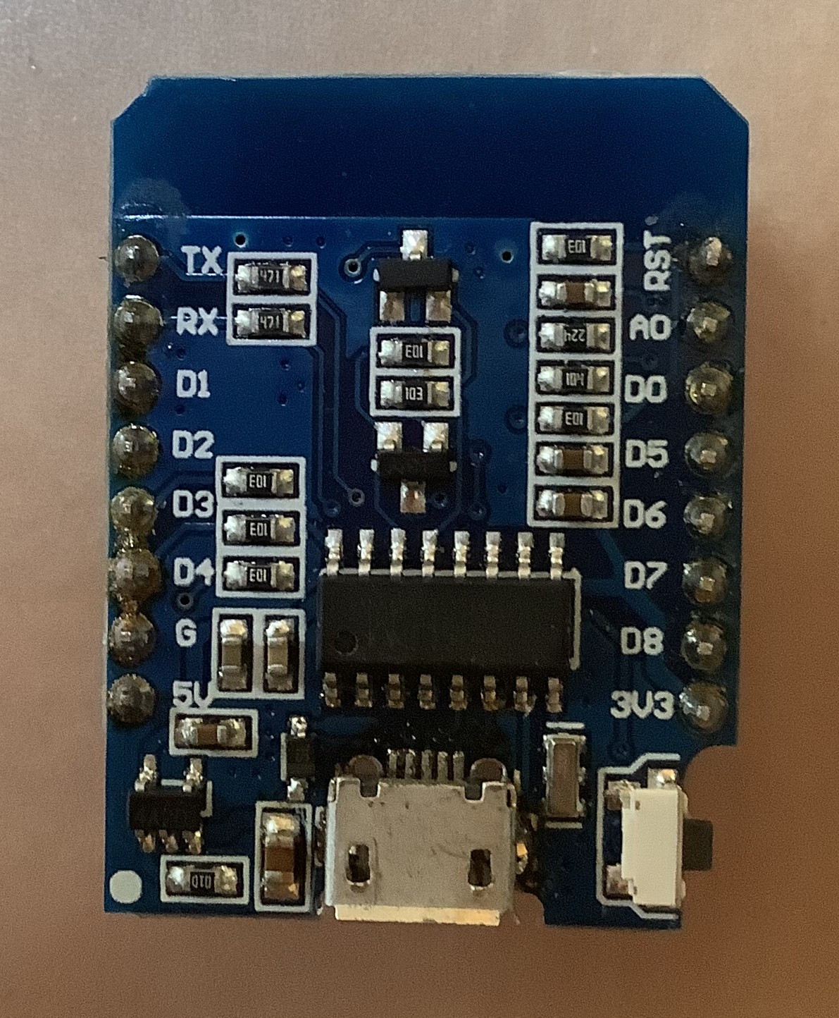
The ME6211C33M5G on-board voltage regulator on the WEMOS D1 (and the clones) that creates the 3V3 rail, feeds the ESP8266 module itself and in this design, also the LoRa module. This is a voltage regulator that, according to the datasheet, should have a 120mV drop-out voltage at 100mA and 260mV at 200mA. I measured that the 3V3 output starts to drop at an input voltage of 3V4, which confirms that. When the LoRa is transmitting however, the current will go up, and the drop out voltage will raise with it.

This limit of at best 3V4 by directly feeding the LiPo cell into the 5V input is reducing the usable capacity of the cell to about half, see the discharge graph above. I want to try to wring some more life out of it, thereby extending the time I need to swap it out.
Technically it works, but for this application it is a no for me.

Supplying the 3V3 input?

Can I use the LiPo cell to directly feed the 3V3 voltage inputs to the ESP and the LoRa module?
The ESP-12F module which is on the ESP8266 WEMOS D1 mini, has a voltage rating of 3.0-3.6V. The E32-433T20D LoRa chip has a voltage rating of 3.0-5.5V. It seems the LiPo cell voltage can drop all the way to 3.1V to have a bit of a safety margin. 

Fully charged, the cell has a voltage of around 4V, which is too high for the ESP module. 
So I can't use the cell directly. 

Using the LiPo with a different supply option

Using an "external" very low-drop voltage regulator will be the answer. 

This seems simple enough, but wait...
The problem to watch out for is going to be back-feeding from the 3V3 regulator on the WEMOS board when I connect the USB cable for debugging or uploading because there is no series diode or diode across the 3V3 regulator as protection on the WEMOS board. The USB 5V has a series diode to prevent back feeding to the connected PC, see below. I need to make sure that the regulator I'm going to use to power everything never exceeds the 3V3 of the WEMOS regulator. That should not be a major issue because my plan is to use a 3V1 supply rail to get more mileage out of the LiPo cell.

Eliminating the USB 5V back feeding into to the circuit

This is only an issue when you connect the circuit to the PC through a USB cable for testing or uploading new firmware. It does no harm, but will mess with the voltages on the receiver board, in essence lifting them up to 3V3. If you want to prevent that from happening, there is a fix. Here is the relevant portion of the schematic that fits most WEMOS variants. There could also be a 100K resistor from the EN pin to GND on some boards.


The 5V comes in through the USB connector and is fed through a Schottky diode (D2) to prevent back-powering the PC when you apply 5V directly to the WEMOS board. (BTW, I have never seen the 500mA fuse used on all the different boards I have).

In any case, the +5V goes to the 3V3 voltage regulator U1 and also to the USB to UART chips.

The three WEMOS variants I have use the CP2104 or the CH340C USB to UART chip. Even though the 5V is going to these chips, they function without it. I tried.

So the most simple solution for the USB power back-feeding into our circuit is to remove the series diode on the WEMOS board, which will prevent the USB supply to feed the 3V3 regulator. This Schottky diode is D2 on the schematic and can be easily removed. I removed it and applied 3V3 to 3V0 to the 3V3 pin on the board to power it and everything, including the USB serial monitor still works on both of these boards.

The location of the diode is pointed to by the arrow for one of my clones.


On the other clone with the CP2104, the diode was located to the right of the 5V pin and is already removed.


With the diode removed, there is no +5V going to the 3V3 regulator on the WEMOS board anymore, so a further refinement could be to also pull the +5V pin on the connector for the WEMOS board to GND, because that will also pull the EN(able) input from the 3V3 regulator down, and disable it. I tried it and it worked, although I did not test the back-feeding by applying a voltage higher than 3V3 and see if the regulator survived.

If you want to go really go fool-proof, you could also remove the ME6211 from the WEMOS board.

Using an external voltage regulator

While searching for a variable voltage regulator with a very low drop-out voltage, I found the TPS73101. The dropout voltage for this regulator is typically 30mV to a max of 100mV at 150mA, and only has 1uA current consumption which is all great. LCSC carries the part so I ordered a few of them which will arrive soon.

The output voltage of the regulator can be set by two resistors. I was planning to use 50K (2 x 100K parallel) and two resistors in series (27K+4K7) for a 31K7 value to set the output voltage to 3.10V, which is sufficient to power the critical components. The parallel resistance is 19K4 and very close to the recommended 19K. Due to the very low drop-out voltage, I'm planning for a 3V2 alarm, so I know it's time to swap out the LiPo cell for a fully charged one.

This also means that I can draw on the LiPo cell for just about the maximum 2000mAh capacity.

The voltage regulators arrived and to try it out in the prototype, I soldered one of them on a DIP carrier board. I then found out that the adjustment to get a precise 3V10 output with fixed resistors is too finicky. You would have to use three in series to get a precise output value so I'm now using a trimmer instead. That, plus some other minor value changes resulted in an updated version of the schematic above.

I took out the sender prototype contraption from the mailbox so I can test a few more things, especially to have a more detailed look at the current consumption. When I'm satisfied, I can start to create a PCB. The current plan is to create one PCB that will accommodate both the sender and the receiver to cut cost.

Change the on-board regulator

One alternative is to replace the on-board 3V3 regulator with a low drop 3V3 version. This will limit the available capacity of the LiPo cell to about 3.35V, but may be a viable alternative. The PCB that I am designing will support that option, you can just leave out the 3V1 circuit components and modify the software.


Current consumption analysis

Analysis may be a big word, but I tried 4 different ESP8266 board after I noticed that the current consumption in deep-sleep was much higher than I expected. I tried all four versions that I have with my prototype. It currently, does not have the LoRa module installed. That will be next.

Here is what I found, while powering the board with 3V2 applied to the 3V3 "output".

GY-D1MINI
This board uses the SIL2104 UART and consumed around 26mA when running in setup and 6.4mA in deep sleep. This is the one that I used on the prototype on my desk and the amount of current in deep sleep got me confused. It has the ESP-12F metal can module mounted on the bottom. It also has an LED installed that is connected to the UART, that cannot be turned off in software, at least I could not find how. There is a D2 on this board that can be removed.

With 6.4mA, this board has the highest deep-sleep current consumption.


D1 Mini clone
This board uses the KH340G UART. It is what I had in the letterbox. This board has the ESP8266MOD metal can module mounted on the bottom. It consumed 20mA in setup and 195uA in deep sleep. There is an unmarked D2 on this board that can be removed.

Apart from the WEMOS D1 Mini V4 below, with 195uA, it has the lowest current consumption in deep-sleep, about double the V4 board below, but that has another significant problem.


Unmarked D1 mini clone
It looks like this board uses the KH340G UART, but the markings are removed. It consumed 19mA during setup and 250uA in deep sleep. It has the ESP8266MOD metal can module mounted on the bottom. There is a D2 on this board that can be removed. Unfortunately, I can't find a schematic for this board. I wonder where the two large diodes just above the USB micro adapter are for.


WEMOS D1 mini V4
This board uses the KH340C UART. This board has a connector for an i2c interface and a USB-C adapter. It does not have the ESP8266 metal can on the bottom but uses the ESP8266EX chip. The board also has a 32Mb SPI flash chip and an ME6211C33 voltage regulator. According to the datasheet, it has a 100mV drop-out at 100mA. 

The board consumed 19mA during setup and just below 100uA in deep sleep. This board has no "D2" installed, so the USB 5V always feeds the on-board 3V3 regulator when connected to a PC. 

With 100uA, it has the lowest current consumption in deep-sleep, about half of the best of the rest.

A real gotcha with this board!

The major draw-back for this board is that it has a different pin-out. The pinout is actually flipped upside down compared to the all the other boards I have, making it somewhat of a tricky layout decision because you can only use the other boards mounted upside down. Compare the bottom markings with the boards above. All the other boards I have were always mounted with the USB connector on top. To do that with this board, you would have to mount it horizontally flipped to keep the RST pin in the upper right-hand corner, and adhere to the same layout. Strange, and a serious cause for a bad layout.


I also have an Adafruit HUZZAH but that does not have a USB connector and AI-THINKER modules which are larger, so are not candidates.


Removing D2, do or don't?
While trying all these boards, I found that there is no urgent need to remove the D2 diode, as long as the voltage rail of the letterbox sender is below 3V3, which it should. Just be careful when you are fiddling with this supply voltage and keep it below 3V3. What does happen when you leave D2 in the circuit and have the USB cable connected to your PC is that the WEMOS board will supply current from the 3V3 regulator to the receiver, and lift the voltage to 3V3. In that situation, you can't test the battery cut-out circuit or accurately measure the current consumption. Keep that in mind.

The overall current consumption of the circuit without the ESP or LoRa is 550uA at a cell voltage above 3.2V, and then goes up to 835uA when triggered. With the ESP at deep-sleep, the total consumption, still without the LoRa is below 1mA.

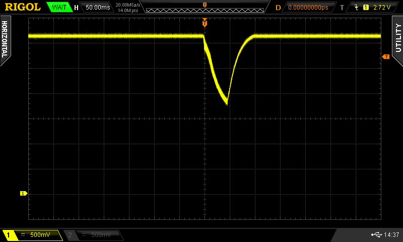
Just measuring the LoRa board by itself shows that when there is no activity, with the ESP in deep sleep, the LoRa board only draws 1.8 uA. When sending, it consumes at least 110mA in bursts for a very short time.  

The screen shot below was taken through a 10R resistor in series with the VCC of the LoRa board, which is fed directly from the LIPO cell, to not produce voltage sags in the 3V1 rail, which could trigger a premature low batt alarm.


Luckily, I don't need to turn the LoRa board power off in the sleep mode.

Protection fuse

I initially added a 100mA PTC fuse in series with the LiPo cell, with an attempt to avoid serious issues that can be caused by connecting a LiPo cell. What you have to take into account however is the voltage drop over the fuse, the tripping voltage and the time before it trips. I'm not an expert at all, but it looks like a 100mA PTC will trip at 200mA and will take about 2.2 seconds before it trips. (this is the part I have and looked at: a radial RXEF020 from Littlefuse) It has a resistance of 1.8Ohm at room temperature.

In deep-sleep mode, the drop is only 1.3mV, but increases to almost 150mV during the LoRa transmissions. 

That's quite a lot for this application, and I don't like the long tripping time, so I'm changing the fuse type to a fast THT Pico fuse of 250mA. Because I'll rather be safe than sorry.

Reverse Polarity Protection

The other safety measure I took was to add protection for a reverse polarity connection with the LiPo cell. I'm using a connector with a key, but not all LiPo cells come with the proper orientation of the wires. That can easily be fixed by swapping the leads in the connector, but you really don't want to have it wrong, hence the addition of a P-FET. The AO3401 has an RDSON of  60mOhm at 4.5V and 85mOhm at 2.5V, so it will be somewhere in the middle. The voltage drop of that device is not a concern.

Rail buffering

With everything connected and working, I looked at the power rails in more detail, because I noticed a sagging when transmitting.
It turned out that I had to use a 1000uF capacitor on the 3V1 rail, and another one on the LiPo rail that supplies the LoRa board, to reduce it considerably.

This is the 3V1 rail without any electrolytes:


One 1000uF added to the 3V1 rail:


Another 1000uF added to the LiPo rail:


This was taken with my Lab Supply with 2ft leads powering the prototype with 3V3.
When I switched to the LiPo that had 4V with very short leads, this was the result:


Obviously, this is with the prototype on proto-board, which is notorious for poor connections, but still...
Something to keep an eye out for. As a result of this observation, I've added a capacitor to the base of the voltage trigger transistor, with an attempt to not let it trigger on a sagging of the rail during transmission.

There may be a potential issue with the power-up of the ESP due to this added capacitance. The chip will go through a voltage ramp-up that may cause instability. I will look at that later in more detail, but right now it does not seem to be an issue.

Update: When I looked at the rails again with the PCB version, there is no more sagging. There is still a lot of hash just about everywhere when the LoRa module transmits, but that seems to cause no harm.


Next step

With the design pretty much done and functioning pretty well in both hardware and software, I started to design a PCB, and I used a board outline based on the Hammond 1593L enclosure I want to use.

However, while thinking some more about the consequence of adding the large electrolytes (or a super cap) on the power rails, and the potential start-up issues for the ESP (it spends some time in the unstable zone due to the slower voltage ramping up), I considered using a voltage supervisor. This chip would keep the ESP in reset until the voltage is stable. While looking into possible candidate solutions, it dawned on me that I could use one as a cell voltage alarm, and eliminate the two transistor voltage sense circuit. Alas, I did not find any with a trigger voltage of 3.2V, and only a single one with an adjustable input that is more or less commonly available, the NCV308MTADJT1G or the equivalent NCP model. I ordered two NCP versions and will try them soon. This chip draws only 1.8uA, so is a significant enough improvement on the power budget as well. Because I was not happy with the two transistor trigger circuit, I redesigned it using a comparator. I will try to add the layout for the voltage supervisor for the trigger so it can be used as an option. When I have the PCB, I can better determine if I need the extra electrolytes and also if the ESP will experience power-up issues.

Initially, I was planning to set the 3V2 trigger level with resistors, but after I changed the resistors to much higher values, I did some calculations for the proper values and decided to make it easier, albeit with the expense of another trimmer. 


The above schematic is what I used to the create a PCB. It has the optional MCP308 voltage supervisor chip that can be used instead of the TS881. Note that I'm now using the WEMOS D1 mini V4 that KiCad supports but with the flipped pinout, because it has the lowest current consumption. Other WEMOS D1 boards can still be used when they are mounted upside down.

The same board can be used for both the sender and the receiver. Several parts can be omitted or added to suit either version.

When I received the boards from PCBWay, they looked perfect as usual. The position of the drilled holes is exactly where they need to be, I always look for that as a quality indicator, and the silkscreen is crisp.

Spoiler alert: I successfully reflow soldered the boards on my new hot plate prototype. That is a project that has been under development for a while, in parallel, and I will start a Blog post as soon as I finish this project.

I build the sender version and started to test it out. The 3V1 adjustment is a little sensitive but easy to do. After having done that, I could now also adjust the 3V2 cell voltage alarm setting. I used a power supply instead of the LiPo cell, so I could finely adjust the voltage and set RV1 to a 3V2 trigger point.

When I then tried the sensor to activate the mail alarm, I noticed a goof in the schematic and subsequent layout. The sensor input is going to the wrong end of C2, meaning that a tilt sensor would continue to keep the 555 timer and the RST signal for the ESP low, not allowing it to boot if the mailbox lid stayed opened due to a large package. I cut the trace and used a small wire to attach the signal to the "right" side of C2, and that worked well. Of course. But that also got me thinking. A tilt sensor has to be positioned a little slanted to make the contacts short when the lid is opened. The lid opens just above 90 degrees in a normal opening position, and about 160-170 degrees when fully open. I was envisioning a 45 degree angle, with the sensor upside down in the open position, which is what I used with the mercury switch as well. 

However, when you use a vibration switch, this all does not matter. So after quite a bit of testing and contemplating, I decided to use the sensitive SW-18010P sensor. I modified the layout to accommodate this change so that will be on the GithHub, making the board more universal.

Below is version 2.3b that incorporates this minor change.


When I tried to activate the LoRa module, I was seeing weird behaviors. It turned out that I made another layout mistake and swapped the board connector 180 degrees. I fixed that for my two modules by removing the connector from the boards, and soldering a new connector to the other side so I could mount the boards upside down. The layout error also has been fixed and is below with version 2.3b. 


With this board, I used the TS881 comparator, not the MCP308 voltage supervisor.

When you think you are done...

When I further started to test everything, I ran into a few more issues. First of all, the comparator worked really well detecting a low cell voltage, but caused an oscillation during the low bat condition. When I applied 3.2V, it triggered but also resulted in a continuous reset of the ESP at this voltage. The rail goes up and down a fraction when the ESP is awoken and the LoRa module transmits. I hoped that the disabling of the 555 timer by software would prevent this, but it didn't. The normal practice is to add some feed-back to the comparator to create a hysteresis, but with the high value resistor values I selected to cut down on the current consumption, this would need to be in the 100M+ range. I don't have these values, and it also really messes with the resistor selection.

So, it was time to activate the optional voltage supervisor and see if that would improve matters. The NCV308 has an internal hysteresis, so that should help.  I calculated a workable set of resistor values and changed the circuit on the PCB and gave that a try. Presto, problem solved! This is a much better solution.

Next I also experienced strange reset issues with the ESP modules. Some of them need a very long reset time, at least 5 seconds. At first I didn't know this, but after some Googling I found that this is normal. This reset issue is unrelated to the voltage rail capacitors on the board. It's just the way it reacts to pressing the on-board reset button. This was kind of strange and unexpected for me, because the other ESP modules I tried earlier had an instantaneous reaction to the button, or shorting the RST pin to ground to wake it up from deep sleep. 

The result of a too short reset pulse was that although a mail or low cell voltage was detected, the WEMOS D1 mini V4 did not fully reset and restart. It did something, because I got some weird characters on the serial monitor (due to the used Baud rate by the kernel). That problem was solved by changing the 555 timer setting to produce a more than 5 second reset pulse. 

And then, I suddenly, out of the blue ran into a myriad of issues (error messages) when I was trying to upload new firmware to the ESP boards. After a lot of searching and head scratching, I figured out that the CH340 driver that is needed for most ESP boards has to be an older version than what I had installed. The latest driver will not work properly with these cloned versions of the CH340, and will give all kinds of communication errors. I had fixed that issue a very long time ago, which is why I couldn't figure it out at first. It turned out that the older driver that I installed a long time ago and worked, got automatically(?) updated to a newer version. Be aware of this issue, it cost me several hours chasing it down. The older version number for the driver that works for me is 3.4.2014.8 and has a date of 8 Aug 2014. Here is a site with a description of the issue and where you can get working drivers: older CH340 drivers.

Because the WEMOS D1 mini V4 had more serious issues with the reset duration, and I also was struggling with the serial port, I tested some of the other ESP boards that I have. Eventually I picked one that did not have the pins soldered in yet, so I could mounted it upside down in the circuit. It worked well, so I just left it there.

To accommodate boards that have this 5s reset issue, I selected the timing components for the 555 timer to have at least a more than 5 sec reset time, using worst-case component tolerances.

Finally, I ran into mysterious reboots when I thought everything was working. It turned out that the sensitive vibration sensor version (SW-18010P) is so sensitive that it continuously activated the trigger circuit and restarted the ESP. It was just lying still and untouched on my desk and still produced random triggers. The very fast needles it produces are very hard to see on the DSO, and I simply missed them for quite some time. Replacing the sensor to the less sensitive version (SW-18020P) solved that issue as well.

So finally I got a functioning receiver and a sender.


To the left is the sender that will go into the mailbox. The lower right white connector is for the sensor, and the upper right one is for the LiPo cell. This board has the WEMOS D1 mini clone installed in the upside down position.

The receiver is on the right, and only has three resistors soldered on the board for the LED's and the reset switch. They connect to the bottom three connectors. Two polarized white ones for the LED's and the middle one for the reset switch. The black round device is the beeper. This board currently has the WEMOS D1 mini V4 installed. 


Final current consumption

With everything working and populated, it was time to do another power consumption analysis.
I applied 3.6V to the sender board with my power supply and measured the current with my DMM.

With both the WEMOS D1 mini clone and the LoRa module added, the total consumption is 1.07mA with both modules in deep sleep mode. With the WEMOS D1 mini V4, the total consumption dropped to 940uA. This is higher than I hoped for, but the best I can do. I'm going to keep the clone installed for a longer testing period.

My assumption is that with a 2000mAh LiPo cell, I would get enough time in-between charges. Time will tell.

The sender is installed in the mailbox and the receiver is on my desk so I can try it out for a few days.


Fitting it in mail box

The mailbox lid sensor types you can use can be two-fold, depending on your mail box and more importantly, the lid. 

Below is a picture of my mail box. The lid is positioned at the top and swings outside to just below 90 degrees. This is a problem for most switches because they may not react well, so you need to position them at an angle. I experimented a lot, even tried the tilt switch with zirconium magnets that would lift the luckily magnetic balls inside the switch free of making contact. However, I did not like that construction at all. I needed several magnets, and they were glued to the lid. They stuck-out too much, and could be broken off when the mail is inserted.

The challenge I have is that I don't have much room, and the construction is severely limiting my activities. Just below the lid is a ledge of about 2 cm, so I can't really position anything below the lid. That would be too easy.

After many attempts, I decided to go back to using a vibration sensor, that is attached to the lid. When the lids drops down into the closing position, it should jolt the vibration switch enough to give me a reliable signal. I contemplated using the sensitive version, and I tried it, but that one is really too sensitive. I suspected that a neighbor ledge dropping down could already trigger mine.

The actual sender enclosure is taped with double sided foam tape to the front of the mail box, There is a ledge above it of about 1.5cm that protects is from heavy mail dropping on top of it. Initially, I located the sender and LiPo in the back of the mailbox, but a large box that was forced into the mailbox, dislocated the sender, so I now moved it to the front. The cable going to the sensor is now too long, so I should shorten it and move it out of the way of the antenna. But, it is working fine so far, and I added the cover of the enclosure box.

There is a short extension cable between the PCB and the LiPo cell. I used that to make the exchange of the cell easier, because it's not so easy to put the plug in when the enclosure is where it is and the cover is on.


Another (last?) improvement

Depending on the sensor type, you need to connect them on either side of C2. When you use a switching type, because it can stay open with large packages, the signal needs to go through C2. Vibration switches on the other hand produces pulses, not a level, and they can be connected either way of C2. I modified the schematic and now include a solder bridge so you can select either type.


The updated schematic and layout


A real gotcha!

While I was testing, I ran into all kinds of seemingly spontaneous triggers, and worse of all, the system would get into a reboot cycle and never went to sleep. So I did not get the mail message, and the cell was draining fast. After a lot of trying and testing on my bench, it would 99% of the time work fine, but as soon as I travelled the 3 flights of stairs down and installed in the letterbox, it would 100% fail and reboot all the time. I traveled up and down the stairs a lot trying to figure it out. 

Because the sensor is mounted on the lid and the leads are going through a small plastic conduct, I would leave that in the mailbox and just took the enclosure and the LiPo cell with me. When I was testing it on my bench, I would simply short the input connector the simulate a trigger. It always worked so I could not find the root cause of the error.

Eventually I got so frustrated that I ripped the sensor with the wire out as well, and put that on my desk. Then I had a hunch that the transmission signal could enter the sensor leads, and indeed, as soon as I wrapped the leads around the antenna a few times, I could verify the reboot problem. The solution of course is to use shielded cable so close to the antenna. When I did that, the problems went away. Keep that in mind.

Testing it out for another week showed no missed mail and it works great.
I have now created a new project on my Github, and put all the information in there. If you think something is missing, leave a message. The details of the project can be found here: Github

Note that when you upload the Gerber files to PCBWay, who is sponsoring this project for me, you'll notice that the Gerber viewer in the upload section does not fully show the picture. When you use their online Gerber viewer, it works fine.

I also created a so called "Shared Project" on the PCBWay website that can be used as well. 
It can be found here:  PCBWay.

Conclusion

We normally don't get a lot of mail, sometimes days without anything, but in the current busy Christmas period we get mail all the time, and the prototype was functioning very well. When I took it out of the mailbox and started to work on the PCB's, we really missed getting the "I have mail" message, that we so quickly got used to it. This is a keeper!