As you are probably aware, there are dozens of solutions available, typically one more complex than the other, in an attempt to make it reliable and fast.
There are basically three schools of thought. One set of die-hards believe in a pure software solution, and others in a hardware solution, the remaining ones, the more practical ones?, use a combination of both.
Using an interrupt to recognize movement can be more responsive, unfortunately, almost all interrupt based solutions use two interrupts. On the Arduino Nano or Mini-Pro, there are only two external interrupts available, so using both can be a problem. The good news is that you really don't always need two interrupts.
If you look at the datasheet, you are presented with perfectly modeled waveforms of the two switches that are central to these mechanical decoders. I'm not discussing the much more expensive optical versions here. Here is a picture of the typical waveforms.
First off, the real wave-forms are not perfectly symmetrical, the output is depending on the mechanical construction and the rotation speed. The other important bit of information is that practically, you rotate the switch from indent to indent.
Here is a screen shot from a one indent move clockwise, captured with a Logic Analyzer:


Notice the different pulse width of the A and the B switches in both cases.
The challenge is to not only detect a rotation movement, a click, but also the direction, and then in such a way that you can also rotate the switch very fast and always be correct.
Using one interrupt
In order to track and visualize what is going on, I added some statements in the code that will generate a trigger pulse so the Logic Analyzer or scope will help us with the timing relationships.
Here is the sketch:
/* Software Debouncing - Mechanical Rotary Encoder */
#include <FaBoLCD_PCF8574.h> //include the i2c bus interface and LCD driver code
//---- initialize the i2c/LCD library
FaBoLCD_PCF8574 lcd; //with this, there are no further code changes writing to the LCD
#define encoderPinA 2 //encoder switch A
#define encoderPinB 4 //encoder switch B
#define encoderPushButton 5 //encoder push button switch
#define Trigger 6 //Trigger port for Logic Analyzer or Scope
volatile int encoderPos = 0;
volatile int oldencoderPos = 0;
void setup() {
pinMode(Trigger, OUTPUT);
pinMode(encoderPinA, INPUT);
pinMode(encoderPinB, INPUT);
pinMode(encoderPushButton, INPUT);
attachInterrupt(digitalPinToInterrupt(encoderPinA), rotEncoder, RISING); //int 0
lcd.begin(16, 2); //set up the LCD's number of columns and rows
lcd.clear(); //clear dislay
lcd.setCursor(0,0); //set LCD cursor to column 0, row O (start of first line)
lcd.print("Rotary Encoder");
lcd.setCursor(0,1); //set LCD cursor to column 0, row 1 (start of second line)
lcd.print(encoderPos);
}
void rotEncoder(){
boolean rotate;
delayMicroseconds(300); //approx. 0.75 mSec to get past any bounce
//delay() does not work in an ISR
//send entry Trigger pulse
digitalWrite(Trigger, HIGH);
delayMicroseconds(10);
digitalWrite(Trigger, LOW);
rotate = digitalRead(encoderPinA); //Read the A-switch again
if (rotate == HIGH) { //if still High, knob was really turned
if (rotate == digitalRead(encoderPinB)) { //determine the direction by looking at B
encoderPos--;
} else {
encoderPos++;
}
}
//send exit Trigger pulse
digitalWrite(Trigger, HIGH);
delayMicroseconds(10);
digitalWrite(Trigger, LOW);
}
void loop() {
//loop until we get an interrupt that will change the encoder position counter
if (encoderPos != oldencoderPos) {
lcd.setCursor(0,1);
lcd.print(encoderPos);
lcd.print(" ");
oldencoderPos = encoderPos;
}
}
And here is a screen shot of a forward indent with the trigger pulses:

As you can see from this data, it takes the Arduino 755 uSec from the A-switch rising edge recognition to the entry into the Interrupt Service Routine (ISR). It then only needs 14.2 uSec to do the rotation recognition.
To put this into perspective, so you get an idea of the relative "blinding" speed of a 16MHz Arduino in relation to slow moving switches:

Turning the knob as fast as I can produces the picture below:

This solution works pretty good, but is not perfect.
A more reliable method, using two interrupts
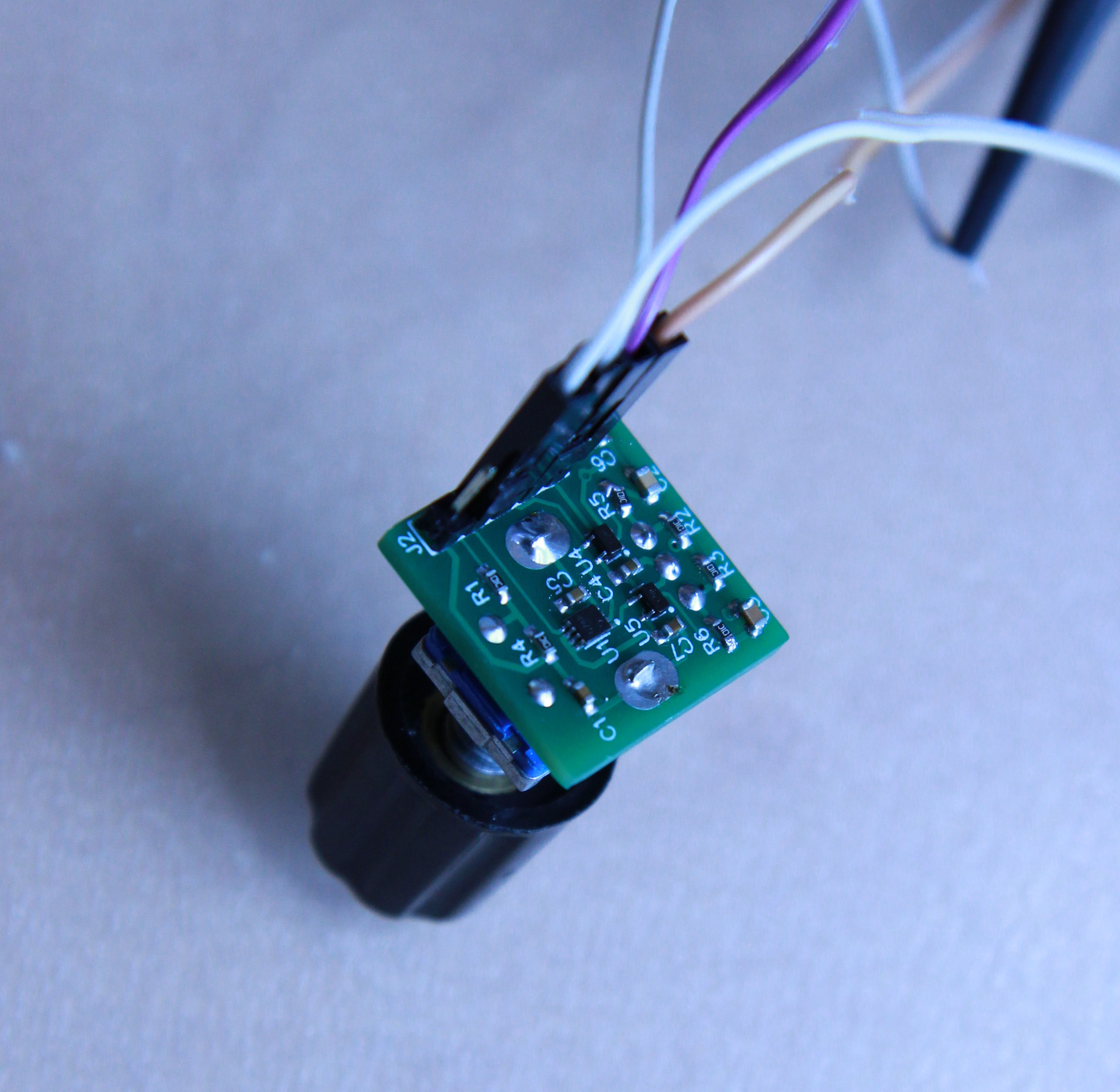
Rotary Encoder with hardware debounce en direction decode
The following is an attempt that uses hardware debounce en encoding to reduce the processing overhead (less false triggers) and can be used on the 8 or 16MHz clocked Arduino's, and also with faster processors like the Raspberry Pi or the ESP processors.
Here is the schematic diagram.

However, is it perfect? Unfortunately no. The switches of very cheap China rotary encoders as the one above are mechanically inferior, but really good ones, typically the optical kind, are expensive. After some testing, I reduced the values of the capacitors to 10nF. In combination with the 10K resistors they are sufficient.
This extra hardware reduces a lot of processing power for the micro-controller, because it reduces the amount of false triggers and is not relying on interrupts, although you could use one on the CLK signal. It could be used in a polling loop as well.
However, when you have bounces like the ones below, all bets are off. These are taken from a cheap no-name rotary switch. In this case, I just used a 10K pull-up resistor to 5V to the switching pin and used GND on the common pin.


Below is an example with a simple and typical 10K/10K/10nF r/c filter like the one in the schematic diagram above. It adequately filters out most of the bounce noise. This is actually taken from an ALPS STEC12E08 version, which is a lot better than the cheap no-name ones. At €2,34 its not that expensive.
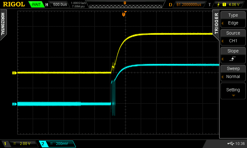
However, even these much better quality rotary switches are not perfect, see below. The blue trace is taken directly from the switch, the yellow trace after the simple debounce circuit. In my opinion, the only solution in that case is to use a combined hardware/software solution. You would have to use pretty long delays after the trigger to attempt a software solution.

It shows that you cannot simply use one-fits-all solutions, you really should try it out, based on your switch and your application.
If you like what you see, please support me by buying me a coffee: https://www.buymeacoffee.com/M9ouLVXBdw
No comments:
Post a Comment