This Blog post will detail the third stage of my project to rebuild the Tektronix SG505 instrument.

Here is the link to the post describing the second version of the design:
https://www.paulvdiyblogs.net/2025/08/diy-rebuild-of-tek-sg505-instrument.html
Here is the first post about this project:
https://www.paulvdiyblogs.net/2025/03/diy-build-of-tek-sg505.html
The reason for the third revision
After the investigations of the second version, I wanted to separate the Power Supply from the Generator in the same enclosure. I also wanted to put the Generator circuits into a full metal enclosure to make the output of the generator as clean as possible and as a minimum, remove the mains hum.
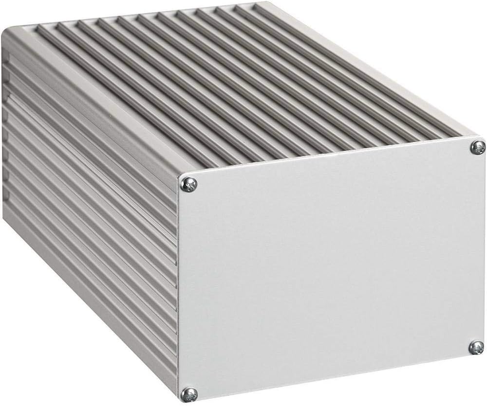
After a very long search, this is the only enclosure I could find that has the required height and width for the front panel layout. It is a ProMa 130 0044 and is also available from Amazon. The outside dimensions are 165x110x80. I would have liked a black enclosure, but alas I couldn't find one. There is one available from ProMa though, with part number 130 0045. I can always spray paint it black myself if I develop the urge. The current Front Panel design will need some modifications and will replace the aluminum panel. The generator PCB will slide in a slot close to the bottom. Unfortunately, the dimensions are a little different so I can't use the current PCB in this enclosure, not even to try it out.
This all means a new PCB for the Generator, for the Power Supply and for the Front Panel.
Splitting the Power Supply
There will be a separation of the noisy mains related parts of the circuit, that need to go outside of the enclosure for the generator. In essence, it means that the transformer, the bridge rectifier, the main capacitor reservoirs and the 40V regulator need to be on a separate PCB that will be housed outside of the generator.
This part of the project will be described in a dedicated post here:
https://www.paulvdiyblogs.net/2025/11/the-diy-sg505-mains-power-supply.html
The shunt supplies for the +/-16V rails can move to the main generator, and also the 12V supply can move to the main board. They are quiet and will have no negative effect on the generator. I hope. It also makes the interface from the Power Supply enclosure simple, because I will only need to use two wires for the 40V supply that feeds the other three rails.
The circuit after the transformer and the bridge will get some more filtering to avoid mains related noise getting into the generator.
The Power Rails on the Generator PCB

(this is not the final version, have a look at the Github site (link below) for the most current information)
No major changes from the previous design, I just added a few extra capacitors and ferrite beads to the power input lines. This may still change a little based on the new layout.
The Generator circuits
The other circuits stay the same, will just get a revised layout and incorporate the three power rails and needs to fit in the new enclosure.
I finished the new version of the generator PCB, now with the power rails on it.

This is what is ordered. On the bottom part you can see that the LM317 is now flipped around and moved closer to the edge of the board. It will be mounted isolated on the side of the enclosure to remove a considerable heat source.
The Front Panel
This is the updated front panel fitting the new enclosure.

The golden rings around the holes connect the front ground fill to the back ground fill to add an EMI shield to the inside circuits.

The rings on the back are larger so will connect to the metal parts of the switches, connecting them to the shield. The 4 mounting holes in the corners also have exposed holes on the back and will connect the shield to the aluminum enclosure.
The enclosure itself is not connected to earth ground but floating. I have created the possibility to connect the GND of the PCB circuits close to the output BNC to an exposed pad on the front panel. In that case, the circuit GND will be connected to earth GND when the BNC is connected to a DSO.
Building up the boards
I received the shipment with the three PCB's and I have built up the power supply by transferring most of the parts from the old board, added the additional parts and tested it. No problems.
The next step was to add the solder paste droplets to the main generator board and transfer the parts one by one from the old board. I used my heat gun to remove them and put them on the new board. When that was done, I reflow soldered the board. Because I used smaller solder paste droplets this time, the reflow process went a lot better, with only a few tiny solder ball bearings and a lot less of the flux gue. I did not clean the board just yet, I wanted to test the functionality first.
Discovering issues
Bad Solder joint
At first I wanted to check the voltage levels of the three power rails. The +16 was only about 9V and then dropped to 3V, the negative 16V was about 30V, the 12V was OK. Although nothing got warm, I quickly shut it off. After connecting the switches and potmeters to the connectors such that the generator could function, I applied power again and saw a welcoming sinewave, albeit with some distortion at the top half. Hmmm, partial good news. When I checked the 16V rails, I still noticed a large unbalance, and that explained the distortion. The good news is that the most complicated circuit seemed to work OK, but the most simple circuit did not, but why?
The hunt for the shunt supply imbalance turned out to become more and more strange. To a point where I started to remove the parts from the shunt supplies one by one, but without any improvement. Using my Lab Supply instead to first power the +16.5V and the -16.5V everything worked, I then supplied the 40V supply, further up-stream and that also showed the correct currents and the system worked fine. Now really puzzled, I used another one of the spare generator boards and started to add the minimum amount of the same parts I just took from the board for the shunt regulator to make it function, which it did flawlessly. Even powering the generator from the second board showed the correct balanced voltages. I was flabbergasted. After thoroughly cleaning the board and resoldering the components back to the board in pairs, everything worked. Bad solder joint!
Wimpy transformer
I also discovered that the mains power supply had a wimpy transformer, so that also needed attention. Details are in the other post:
https://www.paulvdiyblogs.net/2025/11/the-diy-sg505-mains-power-supply.html
Mistake on the front panel
When putting everything together, I first mounted the construction for the main potmeter and the reduction unit. It fitted perfectly, unlike with the first front panel. So, happy with that result, I added all the other switches and potmeters and proceeded to slide the board into position, when I hit a barrier.
Turns out that I made a serious measurement mistake with the position of the rotary switch for the multiplier. It was bumping to the board and also bumping to the reduction unit. Moving the hole up and left solved that issue, but it will mean another turn of the front panel.
This is how it looks now, so close...

This is the inside view of the now fully working instrument:

Mains related hum
When I did the first FFT tests, I still saw some 50Hz hum and some harmonics. When touching the metal parts of the front panel, it got sometimes worse, sometimes better. I did not have the main potmeter knob mounted, and when I touched the metal axel, the hum got worse. Connecting the Earth GND from the output BNC to the metal parts of the main potmeter and reduction unit with a wire did not do anything, but connecting it to the common GND of the main board reduced the hum dramatically.
It turned out that the mounting holes for the main potmeter support and the reduction unit did not connect the metal parts to the common ground of the PCB. I used star washers on each support to improve that. I also added a blank ring to the layout around one more hole of the contraption to improve that going forward.
Connecting earth GND to common GND?
I intentionally connected the front panel shielding to the metal enclosure to create a Faraday cage, but I separated it from the common GND of the board.
In my current setup, with the USB connected EMU0202, however, that produced too much unwanted mains related hum.
I already added a solder tab on the back of the front panel as an option to make the connection possible. When I soldered a wire to it, and connected the other end to a solder lug I added to one of the supports for the main potmeter to connect the two GND's together, it solved the hum issue completely. But now the instrument is earth grounded through the EMU to the laptop, which by the USB-C cable to the power supply is connected to earth GND.
The other possible connection for the instrument to get earth GND connected is through a BNC cable to a CRT or DSO and that will connect it to earth GND as well.
The original SG505 has a switch to connect the common GND to earth GND. If you also want to have the option to separate or connect the enclosure from earth GND, you could add a toggle switch to the back of the unit, or a sliding switch on the side. I'm undecided at this moment, but it's easy to add afterwards.
Result after the fixes
After all these mishaps and corrections, I wanted to share the first FFT from the generator, hot of the press. Note that I was able to quickly trim the second Harmonic visually into oblivion (0.00002%).

Result, no hum, no noise.
Unfortunately, with H2 visually gone, H3 is now sticking out, but the rest of the harmonics are virtually invisible.
During my testing with the updated power supply and mounting everything on the front panel a few times while fixing things, I noticed that I could no longer adjust the H2 harmonic as low as it was above. There is now also some hum visible, so when the new supply arrives, I will look at it again in more detail.
Just for reference, my DIY version of the generator seems a bit better than the original one. Albeit using different measurement tools.

I'm almost there...
Building the final version

Happy with all these results, I uploaded the updated power supply V4 and the updated front panel to PCBWay for production. They gracefully continue to sponsor my activities, despite my screw-ups.😇
It will usually take about a week for the shipment to arrive.
I got the front panel, but made a mistake ordering the power supply board, so that will come in another week. See the dedicated Blog post for that part of the project here.
In the meantime, I started working on the various BOM's, including an off-board one for the front panel parts. They, and all other information will be on my Github site that I will publish when I'm done.
I have been using a lot of parts I already had, but needed to find parts that I could put on the BOM so others can order them. Here are some details for the off-board parts.
Output signal potmeter
One of the challenges was to find a potmeter for the output volume with a switch, that is activated at the end of the rotation. Most of the ones I found switch at the beginning, at 50 degrees according to the specifications.
I put one together with parts I had from a previous life, and that looks like this:

These potmeters come in separate segments you can take apart so you can create stereo versions, or use two different resistor values, and optionally also add a switch segment. I was able to turn the switch segment around to get the right action. To have the switching indent at the end of the range is more natural, because the switch fixes the generator output by a resistor divider just below the maximum output. This is also how the original SG505 has it. I put a potmeter in the BOM with a SPDT switch, but it will be activated in the beginning of the rotation. If you are able to find a potmeter with the switch activated at the end of the rotation, let me know in a PM so I can share it with others.
Mounting the main board
Fixing the OLED display to the front panel
Do not mount any of the other parts to the front panel yet. It allows you to handle it and the fragile display easier.
I first used a black permanent marker to color the inside of the rectangle in the panel pitch black. Do that from the inside so you don't smear ink on the face side.
Make sure you can power the display from the main board while positioning it so you can see where the text is, relative to the viewing area. It will be virtually impossible to position it correctly otherwise. If your main generator board is not inside the enclosure with the 12V regulator cooled by it, you have to use an external heat sink, because the regulator will get too hot otherwise.
Using glue
You can try to glue the OLED display in position to the new front panel. You need to add some glue (not instant glue) sparingly(!) so it does not flow into the visible area when you gently(!) press the two together. Add the glue on the front panel backside. Power the display so you can see what needs to be visible and position it horizontally, put it in position, and keep it there until the glue is dry enough. I first tried that, but abandoned it.
What not to do
In my earlier glue attempt, I used a washing cloth clamp to secure the OLED display in position when letting the glue harden. We'll that seemed to have destroyed the display because it turned black. I first thought that the clamp must have pressed too hard and damaged the flexible cable connection between the glass and the PCB. I had no spares so needed to order a new display.
Well, after the new display's arrived, none of them worked. Tongue in cheek and red faced I have to admit that it wasn't the display. While trouble shooting, I measured the SDA and CLK signals with my DSO and I measured 5V on the display PCB with my DMM, so I started on a rat race trying to find the issue. After a while searching, it turned out that the crimping of the GND wire on one side of the interconnect cable was bad and must have disconnected while I was clamping to let the glue dry. Although visually the crimping looked OK and I did not look further, but searched for other causes. Long story short, what I did wrong was that I connected the GND of my DMM to a GND pin on the main PCB, in effect bypassing the bad GND wire connection when measuring the 5V. I did the same with my DSO, but that still showed the presence of signals so I did not look further. I replaced the GND wire in the extension cable and did a better job crimping the connecter and all is well again.
In hindsight, it's probably safer to use some normal Scotch tape to keep the OLED display in position while the glue is drying. Or, don't use the glue method at all.
Using Scotch tape
I ended up using Scotch tape to secure the display, I used electrical tape earlier but that's too flexible and the display sagged down a bit.
In the picture below, I used another PCB on top of the front panel so I could position the OLED board better. In my case, the distance between the top of the OLED board and the top of the front panel was 20.78mm. You can easily check the horizontal adjustment that way by sliding the display horizontally into position. Because I used clamps to press the two boards together, I could rather easily adjust the vertical and horizontal position of the OLED display within the rectangle opening. To do that you have to power the OLED display from the main board so you can see where the text is.


It does not look very pretty, but does the job and is not permanent.
Assembling the front panel
Do not fasten the front panel to the enclosure just yet. First mount the switches with their cable harnesses already in place, with the solder ends shrink-wrapped for sturdiness. Ask me why. Mount the Vernier potmeter and the volume potmeter. Solder an about 8-10cm thick ground wire to the solder pad on the back of the front panel, with the wire going upwards.
Mount the rotary switch into position with the connected wires on the top side, away from the main board.
Get the front panel roughly in position to the enclosure with the main board already in place. Solder the other side of the ground wire to a solder lug you should have installed on one of the mounting screws of the potmeter delay unit. Take one of the screws that have a ground ring on the bottom so there is a solid ground connection. Check with an Ohm meter for only a few Ohms max. between the front panel exposed holes to one of the GND test pins on the main board and the outer ring of the BNC connector.
You can now connect the wire harnesses from the 0/-10dB switch to their locations. The wiggling room is very tight which is why it should be clear by now that you should not have fully mounted the front panel yet. Then connect the output on/off switch connector. At this point, make sure the switch operation is correct, because you can still turn them 180 degrees to fix that. The other connections are not critical, so you can now mount the front panel into position with the two screws going into the bottom half of the enclosure.
You can now add the ring and nut for the BNC connector and tighten it lightly such that the main board is flush against the front panel. You should have tried this position already when you mounted the voltage regulator to the side of the enclosure such that you don't put too much force on the leads of the LM317. With the front panel mounted, you can now also mount the LM317 into position. Remember to not forget the isolation! Double check again that the metal tab is indeed isolated from the enclosure.
You can now connect all the other wire harness connectors and add the knobs into position.

Calibration procedure
Now it's time to add power and check all controls and that the switches are in the correct working position.
By now, you should have a sinewave output and the counter should show the frequency. If all the controls work correctly, it's time to let the unit warm-up for at least 15 minutes. After that, it's time to finely adjust the 44V main rail, while measuring the voltage on the main board using the +Vreg and -Vreg test points. Adjust the rail voltage with the trimmer on the main power supply board.
With that done, you can now verify the voltages of the +17V and -17V rails. They should be within 0.5V of each other and 17V +/- 100mV. If not, you can change the resistors that are setting the voltage for the TL431's. If you installed the optional trimmers, you can set both rails as close as you can to +/-17V and equal to each other.
To adjust the 2nd harmonic adjustment, you need to use an FFT to see the effect. With the unit now sufficiently warmed-up and the rails adjusted, you can trim the 2nd H trimmer for a minimum height or dB value. You probably have to use some averaging of the measurement to see it well.
Now we can calibrate the 0dB output level. Select the 0dB output level with the switch. Select the Cal position switch setting on the output potmeter. Connect the output of the generator through a 600 Ohm in-line terminator to a DMM in the AC mode. Select the 1KHz frequency on the generator, because the DMM will most likely be precise at this frequency. Adjust RV2, the 0dBm adj. trimmer for a reading of 0.77459Vrms or 0dB.
Verify that the -10dB output switch setting results in about 0.24494Vrms or -10dB.
Change the output value potmeter out of the calibration setting, and verify that you can adjust the output from just over 1.0Vrms down to 300mVrms.
With a 1.000KHz frequency output in the X1K range, and the Freq Vernier in the middle, verify that the Freq Vernier setting has a range of at least +/- 10Hz from the set frequency or 20Hz in total.
Verify that switching to the X100 range shows a frequency of 100Hz +/- 5%. Switch to the X10 range and verify that the frequency is 10Hz +/- 5%. Switch to the X1K setting and verify that the frequency is 100KHz +/- 5%. If not in that range, you can change the value of C19 and C26, but make sure they are matched in value.
That concludes the calibration and verification of the unit.
Final steps
In the meantime, the new power supply boards arrived and I built one up. The details can be found here.
I now have a fully functioning setup and will show some more measurements soon.

Final results

H2 is 0.000048%.
H3 is 0.00031%
H5 is 0.000025%
H6 is 0.000024%
Total THD is 0.00033%, THD+N is 0.0024%
No mains related hum.
I think this is not bad at all, and using my tools, it seems even better than the original.
It took a while, but in the end, I'm very happy with the result.
I added this project to the Shared Project on the PCBWay website so others can easily participate:
Shared Project DIY SG505
Shared Project DIY SG505 Power Supply
Because I think this is an interesting instrument to have on your bench, I also added it to the yearly PCBWay contest that will give it some more visibility.
Here is the setup on my instrument bench:

There is a Github project with all the information you need to build this instrument.
If you like what you see, please support me by buying me some Java: https://www.buymeacoffee.com/M9ouLVXBdw
For those that already did, thank you!
2 comments:
Hi Paul, I came across your blog and your project looks amazing! I'm Emily from PCBWay and I was wondering if we could collaboration again. We'd love to support your project with our services. If you are interested in it, feel free to reach out to me at marketing@pcbway.com
Congratulation Paul. Very impressiv.
Post a Comment