Show by Label

Thursday, September 29, 2016

Building a Kelvin-Varley Divider


When I restarted my hobby, I did not have very precise (expensive) equipment, and initially, really didn't want to spend the money to obtain it. 

Initially, I wanted to spend the limited hobby funds on parts to tinker or build things with. However, every now and then I need something with a precision or resolution that I can't deal with. Typically, I mean precise voltages and precise resistances. With these two, one can also obtain precise currents by applying Ohm's law.

I recently spend a relatively large sum (for me) to obtain a bench multi-meter with a much higher precision than the DMM's I already have. They are all 3.5 digit, and I wanted to go one step above that.

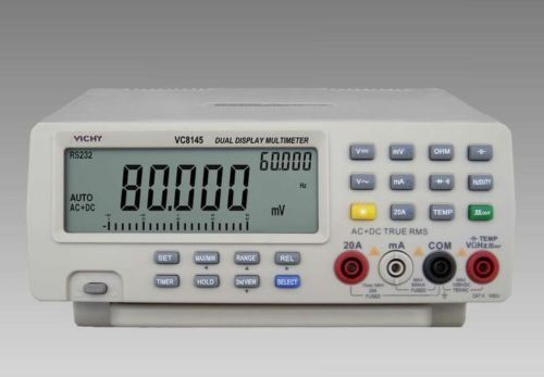
After a long search and discounting used (they need calibration typically costing 100 Euros) instruments, I decided to take the plunge on a VICI VC8145 Bench DMM. It has a 4-7/8 digits display with 80,000 counts. The precision in the DCV meter is 0,03% and 0.3% in most other measurements. I purchased one for about 150 Euro's from eBay. It served me well for many years.


New-VICHY-VC8145-DMM-Digital-Bench-Top-Multimeter-Meter-PC


In 2021 I sold the Vichy and upgraded it to a SIGLENT SDM3065X 6-1/2 digit DMM, which shows that my demands seem to go up in time, and so does the budget allotted to the hobby. 😉


Every now and then, even this is not enough when your trying to deal with a reference that needs to be 10x or better to calibrate things. As an example, I purchased a few inexpensive but precise voltage standards, the best one is the KKMOON variant with the AD584KH, and a more simple unit that has the even better AD584LH.


Google for "KKMOON AD584 Reference"
There is also a blog with a discussion about this unit here: https://www.eevblog.com/forum/beginners/t17704/


This reference is calibrated and you get the calibration details for the 2.5V, 5V, 7.5V and the 10V.


(I modified my reference with a switch and adjustment capability for the 2.5 reference voltage level, per the data sheet of the AD584) Wit this I can tune the voltage reference without disturbing the originally calibrated values. I also replaced the banana sockets)


Note: the switch is not pushing the PCB up, it's not even touching it. There was just enough room between the PCB and the Li-Ion battery (;-))

With this calibration information, you can check your equipment and see how accurate it is against this reference.

My unit listed the 10V output as 10.00673 which translates to an accuracy of +0.0673%. Now, in some cases, I have a need for a precise 10.00000V to make calculations easier, or to be used with an ADC or DAC reference or input. I can't deal with that with my new DMM, it's not accurate enough, and I need more digits.

Same with precise resistor values, how do you make sure that a resistor is 0,01% or better if your instrument is "only" 0,3%. It needs to be 10x better, so 0,001% or better.

Well, the answer I hope to have found is using an instrument that was designed 100+ years ago, the Kelvin-Varley Resistance Divider. Google it if you have never heard from it.

I studied the little information there is about this concept, and really looked in detail to the best standard still, the Fluke 720A. Obviously, even used, this is beyond my reach and most others.
However, I also found an article that was written 20 years ago, that detailed a DIY instrument, and I decided to give that a try.

There are actually two instruments described on this site. One is the KV and one is the Null Detector. I build both.
The articles can be found here: http://conradhoffman.com/mini_metro_lab.html
It provided the missing link for me.

The Null Detector Amplifier is described on the Blog separately.

Kevin-Varley Resistance Divider
Back to the Kevin-Varley Resistance Divider. I hope that by now you will have read the article, and I also suggest you have a look at the Fluke 720A documentation to get a feel for the complexity in dealing with 1ppm precision. Search Google for the 720A manual.

The Fluke 720A


All the way in the back of the 720A manual are the circuit diagrams. In essence, this is the simplified 720A circuit:


The Fluke 720A deviates from the original Kevin-Varley specification (look that up) and so does Conrad's design. The original specification was meant to be for resistor chains without a shunt. The lower resistance of the last decades also meant that the output impedance was as low as possible, because the only device -at the time- connected to it was a galvanic meter as a null detection meter.

We now have DMM's with 20GOhm loading so we can increase the values of the lower decades somewhat. Conrad used easy to obtain resistors, and I followed his design as close as possible with one exception, I could not get 412 Ohm resistors with 1% and 0.5W, so I used 422 Ohm. This meant that the shunt had to be redesigned but that's quite simple to do.

Here is my version of the circuit diagram :
There are a few more changes/additions that were mine. First of all, I added jumpers to "break" the shunt accros the decade resistors. This will allow you to measure and compare each individual resistor in addition to the shunt. Second, I added a buffer circuit to avoid loading the output of the divider. I can switch this in and use lower impedance meters at the output. I also added test points for my DMM clips next to the 4mm banana sockets.

Lastly, I did not use Conrad's connectors, but the more easily available connector strips.

Here are pictures of my first proof-of-concept build:


With this setup, I could start to play with this instrument and see if it indeed could deliver on my expectations. I had never used (not even heard of) a KVD before, so I had a lot to catch up with.

Resistor selection and matching
The biggest and most laborious job is the selection and matching of the resistors. It's not difficult, it just takes time and a lot of patience. What I found was that you should not skimp on the quality of the resistors.  Initially I did not want to use expensive low PPM/C super precision resistors for my proof-of-concept prototype. However, my supplier of choice send me a set of resistors in the 10K and 100 Ohm range that obviously came from a cheap source.; You can guess where from. The values were all over the map. As an example, from the 200 10K resistors, exactly half of them were outside the 1% specification. One resistor was even 10K3 Ohm. Not only that, there was no way I could get a matched set within 0,003% with this lot. They were awful.

Here is a picture of the Gaussian distribution :


The vertical arrows on the left and right stickers denote the 1% borders. Anything to the left or right is out of specification, and there are about 50 resistors that fell of the board, literally.
Luckily, my supplier was quick to acknowledge my issue and send me a new set. What they recommended was to get 0.5 or 0.6W versions, as they are more precise (actually, from another factory) The 100 Ohm resistors were equally bad, but I didn't need the precision. This new lot did contain a good enough set of matched resistors.

This is a picture of what a typical Gausean distribution really should look like:


Wheatstone Bridge
Per Conrad's instructions, I used a Wheatstone bridge to select and match the resistors as precisely as I could.

After some matching using his method, I decided to used another bridge concept to be able to more easily switch from resistor values, and simply increase the resolution of the bridge.


Here are two pictures to save some words:


The shunt connections are made with jumpers, and you move the jumpers as a pair to shunt the potentiometer with decreasing resistor values. After I selected a group of resistors for a KVD decade that were in the same ball-park, I then matched them among that set for the closest values. To calibrate the bridge, one resistor of the set was used as the Reference resistor, and one of the others as Rx. I then nulled the bridge with the lowest resistor shunt possible. After that I used the other resistors in the set and noted the deviation of the null (+ and -) to select the closest set.

Note that when the KVD is finished, you can use it instead of this potmeter contraption.


The K-VD resistor sets
The 10K set needs the best matching and the spec says 0.0037%. I was able to get close to 0.001%, however, the actual values of the resistor set were around 9,950 Ohms. This is within the 1% specification (0.5%), but not close enough to 10K.

During my first tests, I didn't get the expected accuracy from the lower decades (they were not multiples of 10x), and so I went back and forth calibrating and trying to figure out what caused it. To try to fix it I started with the first 10K decade and used 49.9 Ohm 1% resistors in series to match the resisters closer to 10K (actually within 1 Ohm of 10K). Although the calibration of the decades starts with the lower ones and then go up, I figured that the relationship may have been distorted so I started from the first decade down. And low and behold that seemed to have fixed my resolution problem.

Proof of concept
There is a lot more to test, but I'd like to give you a quick answer to the challenge I posted in the beginning. If you have a 10.00673V calibrated reference, can you use the K-VD to calibrate another reference to a precise 10.00000V without using a 6 or 8 digit DMM?

The short answer is, yes you can. At least that is what I was able to do (I think).

Following are the steps I took.
I connected the output of the 10.00673 reference to the input of the K-VD. The output of the K-VD was connected to the input of my 20GOhm input bench DMM. (virtually no loading, so I could cheat and not using a bridge) The KVD decades were set at minimum subtraction or division with 9-9-9-9-9-10. My DMM showed 10,007V at the output which is the best it can do.

A quick-and-dirty procedure (thank you Unknown for pointing this out) is to calculate the setting of the K-VD to create a precise 10V output as follows:
10.00000 / 10.00673 = 0.999327  K-VD setting: 9-9-9-3-2-7
This sets the divider ratio to 0.999327 and the output voltage would therefore be:

10.00673 * 0.999327 = 9.99999547071, which is close enough.


My expectation is that the output went from 10.00673 to 10.00000V, but there is currently no way for me to verify that. I need a much higher resolution voltmeter to do that. So the next project was born, a high resolution DMM.
Look here for that follow-on project : building-6-digit-digital-milli-voltmeter

Note that the proper procedure should be as follows:
You would need to use a Wheatstone bridge between the calibrated reference and the new reference, and use the K-VD as one arm of the bridge. Set the K-VD to the right value, and null the bridge by adjusting the output of the new reference, which should result in the desired output of 10.00000V.  This method is preferred because it avoids currents flowing through the bridge which will eliminate a number of issues.

So in my own terminology, we are now able to "transfer" a calibrated voltage from one reference to another secondary one without using expensive precision equipment. If you build the Null Meter, you could potentially do this with your 3.5 digit DMM.

There are a few other applications for the K-VD that I may try to cover in more details later, but don't hold your breath. It may take a long time for me to get around it with so many other projects and interesting things to discover.

In the meantime, I started the process of building a DIY simple but fairly precise 6 digit Digital Voltmeter, and that project can be found in another post.


In the future, I may upgrade the K-VD with even better components and a PCB. Don't hold your breath though. There are so many other projects that are on the Bucket-List...

Enjoy!

If you like what you see, please support me by buying me a coffee: https://www.buymeacoffee.com/M9ouLVXBdw

Monday, June 13, 2016

_HowTo: Simple Method to Log Charging and Discharging of Li-Ion and Lipo cells

For my Raspberry Pi automatic power supply design with a UPS function (see another post), I wanted to learn more about the charging and discharging characteristics of Li-Ion and Lipo cells.

In several of my supply designs, I use the Adafruit Powerboost 1000c circuit. It uses an MCP73871 charge controller, that is set to deliver up to 1 Amp of charge current. It does not use a Thermistor to monitor the cell temperature, and I wanted to use a variation of cells.

The cells I tested were a TR 18650 with 2400mAh, a TR 14500 with 1200mAh, both are Li-Ion cells, and one small Lipo cell, model 043040 with 500mAh.

Before I modified the Powerboost circuit to limit the charge current to 500mA or a little less, I wanted to profile the charge/discharge characteristics of these three cells.

I used a RPi Model 3 powered by my automatic UPS supply, and I used another RPi, a Model (1) B, together with an A-2-D convertor circuit to monitor the current of the cells powering the Model 3.

The monitoring circuit is based on yet another post, and modified to measure the cell voltage together with the charging or discharging currents. Here is the circuit:

I used the following Python script to show the progress on the console and log the results into a file that I could upload to Excel to graph curves.


#!/usr/bin/python
#-------------------------------------------------------------------------------
# Name:        MCP3002 Measure 5V
# Purpose:     Measure the voltage and current of a Li-Ion cell
#
# Author:      paulv
#
# Created:     22-10-2015, Modified 10-06-2016
# Copyright:   (c) paulv 2015, 2016
# Licence:     <your licence>
#-------------------------------------------------------------------------------

import spidev # import the SPI driver
from time import sleep, time, strftime
import subprocess
import sys
import os

# ==== constants
__author__ = 'Paul W. Versteeg'
VERSION = "1.0"

DEBUG = False
vref = 5.0 * 1000 # V-Ref in mV (Vref = VDD for the MCP3002)
resolution = 2**10 # for 10 bits of resolution
cal_CH0 = 0 # calibration in mV
cal_CH1 = 0
interval = 10       # interval between measurements in seconds
sample_interval = 2 # interval between samples in seconds
log_interval = interval - (2 * sample_interval) # log interval in seconds

# MCP3002 Control bits
#
#   7   6   5   4   3   2   1   0
#   X   1   S   O   M   X   X   X
#
# bit 6 = Start Bit
# S = SGL or \DIFF SGL = 1 = Single Channel, 0 = \DIFF is pseudo differential
# O = ODD or \SIGN
# in Single Ended Mode (SGL = 1)
#   ODD 0 = CH0 = + GND = - (read CH0)
#       1 = CH1 = + GND = - (read CH1)
# in Pseudo Diff Mode (SGL = 0)
#   ODD 0 = CH0 = IN+, CH1 = IN-
#       1 = CH0 = IN-, CH1 = IN+
#
# M = MSBF
# MSBF = 1 = LSB first format
#        0 = MSB first format
# ------------------------------------------------------------------------------


# SPI setup
spi_max_speed = 1000000 # 1 MHz (1.2MHz = max for 2V7 ref/supply)
# reason is that the ADC input cap needs time to get charged to the input level.
CE = 0 # CE0 | CE1, selection of the SPI device

spi = spidev.SpiDev()
spi.open(0,CE) # Open up the communication to the device
spi.max_speed_hz = spi_max_speed


def read_mcp3002(channel):
    '''
    Function to read the data channels from an MCP300 A-2-D converter

    Control & Data Registers:
    See datasheet for more information
    send 8 bit control :
       X, Strt, SGL|!DIFF, ODD|!SIGN, MSBF, X, X, X
       0, 1,    1=SGL,     0 = CH0  , 0   , 0, 0, 0 = 96d
       0, 1,    1=SGL,     1 = CH1  , 0   , 0, 0, 0 = 112d

    receive 10 bit data :
       receive data range: 000..3FF (10 bits)
       MSB first: (set control bit in cmd for LSB first)
       spidata[0] =  X,  X,  X,  X,  X,  0, B9, B8
       spidata[1] = B7, B6, B5, B4, B3, B2, B1, B0
       LSB: mask all but B9 & B8, shift to left and add to the MSB

    '''

    if channel == 0:
        cmd = 0b01100000
    else:
        cmd = 0b01110000

    if DEBUG : print"cmd = ", cmd

    spi_data = spi.xfer2([cmd,0]) # send hi_byte, low_byte; receive hi_byte, low_byte

    if DEBUG : print("Raw ADC (hi-byte, low_byte) = {}".format(spi_data))

    adc_data = ((spi_data[0] & 3) << 8) + spi_data[1]
    return adc_data


def write_log(msg):
    '''
    Function to create a log of the readings with a time stamp.

    The fiels are seperated by a tab, so the file can be easily imported into
    an Excel spreadsheet to graph the results.

    The log results are appended, so the log file should be deleted for every
    measurement.

    '''
    try:

        dstamp = strftime("%d-%m-%Y")
        tstamp = strftime("%H:%M:%S")

        # open the log file and append results
        with open("/home/pi/lipo.log", "a") as fout:
            # Tabs are used to seperate the fields so technically it's not a real CSV format.
            # MS-Excel reads it anyway.
            fout.write (str(dstamp)+"\t"+(tstamp)+"\t"+str(msg)+"\n")

    except Exception as e:
        return(1)


def main():
    try:
        # create and setup the log file
        if not os.path.isfile('/home/pi/lipo.log'):
            # create the file and set the access mode
            subprocess.call(['touch /home/pi/lipo.log'], shell=True, \
                stdout=subprocess.PIPE, stderr=subprocess.PIPE)
            subprocess.call(['chmod goa+w /home/pi/lipo.log'], shell=True, \
                stdout=subprocess.PIPE, stderr=subprocess.PIPE)

        write_log("\n===== Starting Log =====")

        print("Voltage and Current log from Li-Ion/Lipo cell")
        print("SPI max sampling speed = {}".format(spi_max_speed))
        print("V-Ref = {0} mV, Resolution = {1} bit".format(vref, resolution))
        print("SPI device = {0}".format(CE))
        print("-----------------------------\n")

        while True:
            # average three readings to get a more stable result
            Vdata_1 = read_mcp3002(0) # get CH0 input (Volt)
            Cdata_1 = read_mcp3002(1) # get CH1 input (Current)
            sleep(sample_interval)
            Vdata_2 = read_mcp3002(0) # get CH0 input
            Cdata_2 = read_mcp3002(1) # get CH1 input
            sleep(sample_interval)
            Vdata_3 = read_mcp3002(0) # get CH0 input
            Cdata_3 = read_mcp3002(1) # get CH1 input

            Vdata = (Vdata_1+Vdata_2+Vdata_3)/3
            if DEBUG : print("V_Data (bin)    {0:010b}".format(Vdata))
            v_result = round((((Vdata * vref) / resolution)+ cal_CH0),2)
            if DEBUG : print ("V_result {} mV").format(v_result)
            voltage = round(v_result/1000.0,2) # convert to mV with 2 decimals
            print("Voltage  : {} V".format(voltage))

            Cdata = (Cdata_1+Cdata_2+Cdata_3)/3
            if DEBUG : print("C_Data (bin)    {0:010b}".format(Cdata))
            Vcurrent = round((((Cdata * vref) / resolution)+ cal_CH1),2)
            if DEBUG : print ("Vcurrent : {} mV").format(Vcurrent)
            current = int(Vcurrent/5) # convert to mA (gain 50, R = 0.1 Ohm)
            print("Current  : {} mA".format(current))
            if DEBUG : print("-----------------")

            # log the results
            msg = str(voltage) + "\t V\t" + str(current) + "\tmA"
            write_log(msg)
            sleep(log_interval) # wait and loop back

    except KeyboardInterrupt: # Ctrl-C
        if DEBUG : print "Closing SPI channel"
        spi.close()


if __name__ == '__main__':
    main()


Here is the charge curve for a tiny 043040 Lipo cell :


This is the one I use: http://www.ebay.com/itm/251493181437

The "noise" that you see on the voltage and current graphs can be caused by the chemical process that takes place. I read somewhere that this is a "noisy" process.

This charge curve shows a charge current that is a little too high for comfort. The specification for the cell ( http://www.powerstream.com/p/H043040SP%20with%20BMS.pdf ) lists a maximum charge current of 1C, but a more safe value is 80% of that. The graph shows that there is a short period of time where the current is more than 630mA, so I needed to modify the Powerboost circuit to lower the maximum charge current.

This is quite simply done by changing one resistor value (R16, located just above the USB connection) from 1K0 to 2K2 (resulting in a maximum of 454mA), unfortunately it is an 0805 SMD component, so not that easy. Here is the schematic of the Powerboost :
https://cdn-learn.adafruit.com/assets/assets/000/024/638/original/adafruit_products_sch.png?1429650091

Here is the charge graph with the limited charge current now topping at 454mA.


 And here the discharge curve for the 043040 cell:


The charge provides about 20 minutes of power to an Rpi-3 (in rest, idling!) at an average of about 450mA consumption current. The Powerboost circuit warns for a low-bat level, and my hardware removes the power from the RPi when that happens. The trip voltage is somewhere below 3.5-3.25V (it varies somewhat depending on the fall-off curve).


Here is the charge graph for a 14500 Li-Ion cell with the unmodified Powerboost:


This is the discharge graph for the 14500 cell:


And finally the charge graph for a Li-Ion 18650 with 2400mAh with the unmodified Powerboost :


And the 18650 discharge graph:


Note that it took 4 hours to charge this 2400mAh cell after it powered the Rpi-3 (idling!) for 3 hrs (at an average of  an 450mA consumption rate). Also notice the almost perfect linear discharge level. I read somewhere that they use these cells for the batteries in hybrid and electric cars like the Tesla.

Enjoy!

If you like what you see, please support me by buying me a coffee: https://www.buymeacoffee.com/M9ouLVXBdw

Saturday, June 4, 2016

_HowTo: Raspberry Pi with auto restart

Based on my one button start-stop design, I modified the circuit so the RPi can be used in autonomous or embedded applications.

https://www.raspberrypi.org/forums/viewtopic.php?uid=52264&f=37&t=150358&start=0

Enjoy!

If you like what you see, please support me by buying me a coffee: https://www.buymeacoffee.com/M9ouLVXBdw

_HowTo: Update on RPi Watchdogs

This post was concocted several years ago to show various ways to make sure applications or the kernel are protected from hang-up issues. Required when you run a server application, security camera or network related devices.


Here is a quick and concise summary of the various ways to use the watchdog functionality.
After all the trouble some of us went through to master the watchdog, it basically distilled down to three different methods.

These three methods cannot be combined because the /dev/watchdog device is claimed by either of the methods.

The watchdog device is already activated at boot time for all three methods.
I tried Method 1 and Method 2, which are RPi specific, on an RPi Model B3+ running Stretch, and on the RPi Model 4 running Buster. Both methods work fine on either RPi. Method 3 is very generic, and only needs one adjustment to avoid a bug.

Method 1

The easy shell method is as follows:
With a little script, you can add protection for kernel and user-space program hang-ups.
You start that process by sending a period "." to /dev/watchdog. This will kick-off what I would call a keep-alive session. You, or your program now needs to continue to send a "." to the /dev/watchdog within a 15 second period. If you don't, the RPi will reboot automatically. You can send the character "V" to the device to cancel this process.

You can use the following command to test this out - watch out however, the RPi will reboot in 15 seconds if this is all you do! :

sudo sh -c "echo '.' >> /dev/watchdog"

Every time you resend this command within a 15 second window, the watchdog counter will be reset. If you stop doing this or wait for more than 15 seconds, the timer overflows, en the RPi gets rebooted.

Creating and activating the following little script (from user sparky777), will protect the RPi for kernel hang-ups.

#!/bin/bash
echo " Starting user level protection"
while :
   do
      sudo sh -c "echo '.' >> /dev/watchdog"
      sleep 14
   done

When this script gets installed by init.d or systemd at boot time, it most likely runs as root so there is no need to do the "sudo sh -c" trick, you can simply use "echo . >> /dev/watchdog" instead.
I took the easy way and installed it with cron. Just add
@reboot /home/pi/name-of-program
and reboot to install.

When this script runs, there is now protection for kernel related issues. This can be tested with the so called fork bomb.
Make sure the script runs.
Simply type the following sequence at a prompt and then hit return to launch the fork-bomb.

: (  ){ : | : &  }; : 

The RPi will reboot in about 15 seconds.


Method 2
The second method with the same functionality can be obtained by using systemd.

To let systemd use the watchdog, and to turn it on, you need to edit the systemd configuration file.


sudo nano /etc/systemd/system.conf 
and change the following line:
#RuntimeWatchdogSec=
to:
RuntimeWatchdogSec=10s
Fifteen seconds is the maximum the BCM hardware allows.
I also suggest you activate the shutdown period protection by removing the '#' in front of the next line.
ShutdownWatchdogSec=10min

After a reboot, this will activate and reserve the watchdog device for systemd use. You can check the activation with :

dmesg | grep watchdog

It should report something like this on an RPi M3+ with Stretch:
[ 0.784298] bcm2835-wdt 3f100000.watchdog: Broadcom BCM2835 watchdog timer
[ 1.696537] systemd[1]: Hardware watchdog 'Broadcom BCM2835 Watchdog timer', version 0
[ 1.696628] systemd[1]: Set hardware watchdog to 10s.
The kernel will now update the hardware watchdog automatically every 10/2 seconds. If there is no kernel activity for 10 seconds, the RPi reboots.
This means that there is a default protection for kernel related issues. This can be tested with the so called fork bomb, see above.

If you want the user-space application protection capability, you have to use the systemd API within your program to do that. This is covered in a later post.

Method 3


The third method is not RPi specific and uses a rather large and sophisticated daemon package (pretty much legacy now) that allows you to set many different parameters that will be able to reboot the RPi. After installation you can use

man watchdog

For more information, or go here: https://linux.die.net/man/8/watchdog

The package needs to be installed first.

sudo apt-get install watchdog

Because this is a wide spread legacy package, I'm not going to cover that in detail here.
To set some of the parameters the watchdog daemon should watch :

nano /etc/watchdog.conf

For the fork bomb test I took away the "#" marks from the following lines:
# This is an optional test by pinging my router
ping=192.168.1.1
max-load-1 = 24
min-memory = 1
watchdog-device = /dev/watchdog
watchdog-timeout = 15
Note: The last line is very important and Rpi specific. If this command is not added, you get a bit of a cryptic error (run sudo systemctl status watchdog.service) :
cannot set timeout 60 (errno = 22 = 'Invalid argument')
This is caused by the default wdt counters used in other Linux systems, mostly handlingt 60 seconds. But because the RPi wdt counter on the SOC only handles a maximum of 15 seconds, this line must be added, otherwise the package won't work at all.
Unfortunately, this is a bug that the Foundation missed and the default 15 seconds should have been programmed into the kernel, or added by default in the watchdog.conf file.


---------------------------------------------------------------------------------------------------------------------------------
Using the systemd API to let a program control the watchdog.

Below I will show how to add extra support for your own (Python) application by using the systemd API and framework.

If you want to use the systemd method of using a software watchdog to add control to your own application program, you can use the following method to implement that.

As I showed above, you use the hardware BMC watchdog system to reboot the RPi when the kernel gets unresponsive, or when systemd is no longer operational.

A higher level of control can be added by a software watchdog. Systemd provides that, plus an interface (API) to implement that.
The combination of the two provide the Supervisor chain (in systemd speak).

There are two steps to implement this method.

1. You need to provide a service configuration file for systemd to instruct it what to do.
2. You need to add a few things to your own application to make it all work in this environment.

In essence, you are going to ask systemd to initiate the watchdog, and your application needs to "ping" it at regular intervals. If the application fails to do that, systemd will take action and can ultimately reboot the RPi.

I wrote a systemd service file that will let you test a number of elements.

# This service installs a python test program that allows us to test the
# systemd software watchdog. This watchdog can be used to protect from hangups.
# On top of that, when the service crashes, it is automatically restarted.
# If it crashes too many times, it will be forced to fail, or you can let systemd reboot
#

[Unit]
Description=Installing Python test script for a systemd s/w watchdog
Requires=basic.target
After=multi-user.target

[Service]
Type=notify
WatchdogSec=10s
ExecStart=/usr/bin/python /home/pi/systemd-test.py
Restart=always

# The number of times the service is restarted within a time period can be set
# If that condition is met, the RPi can be rebooted
#
StartLimitBurst=4
StartLimitInterval=180s
# actions can be none|reboot|reboot-force|reboot-immidiate
StartLimitAction=none

# The following are defined the /etc/systemd/system.conf file and are
# global for all services
#
#DefaultTimeoutStartSec=90s
#DefaultTimeoutStopSec=90s
#
# They can also be set on a per process here:
# if they are not defined here, they fall back to the system.conf values
TimeoutStartSec=2s
TimeoutStopSec=2s

[Install]
WantedBy=multi-user.target

Details can be found if you look for systemd.service(5)


I also wrote a Python script that lets you play with this system and experiment to you hearts delight.

#!/usr/bin/python2.7
#-------------------------------------------------------------------------------
# Name:        systemd daemon & watchdog test file
# Purpose:
#
# Author:      paulv
#
# Created:     07-05-2016
# Copyright:   (c) paulv 2016
# Licence:     <your licence>
#-------------------------------------------------------------------------------

import sys
import os
from time import sleep
import signal
import subprocess
import socket

init = True

def sd_notify(unset_environment, s_cmd):

    """
    Notify service manager about start-up completion and to kick the watchdog.

    https://github.com/kirelagin/pysystemd-daemon/blob/master/sddaemon/__init__.py

    This is a reimplementation of systemd's reference sd_notify().
    sd_notify() should be used to notify the systemd manager about the
    completion of the initialization of the application program.
    It is also used to send watchdog ping information.

    """
    global init

    sock = None

    try:
        if not s_cmd:
            sys.stderr.write("error : missing s_cmd\n")
            return(1)

        s_adr = os.environ.get('NOTIFY_SOCKET', None)
        if init : # report this only one time
            sys.stderr.write("Notify socket = " + str(s_adr) + "\n")
            # this will normally return : /run/systemd/notify
            init = False

        if not s_adr:
            sys.stderr.write("error : missing socket\n")
            return(1)

        sock = socket.socket(socket.AF_UNIX, socket.SOCK_DGRAM)
        sock.sendto(s_cmd, s_adr)
        # sendto() returns number of bytes send
        # in the original code, the return was tested against > 0 ???
        if sock.sendto(s_cmd, s_adr) == 0:
            sys.stderr.write("error : incorrect sock.sendto  return value\n")
            return(1)
    except e:
        pass
    finally:
        # terminate the socket connection
        if sock:
            sock.close()
        if unset_environment:
            if 'NOTIFY_SOCKET' in os.environ:
                del os.environ['NOTIFY_SOCKET']
    return(0) # OK


def sig_handler (signum=None, frame = None):
    """
    This function will catch the most important system signals, but NOT a shutdown!
    During testing, you can use this code to see what termination methods are used or filter
    some out.

    This handler catches the following signals from the OS:
        SIGHUB = (1) SSH Terminal logout
        SIGINT = (2) Ctrl-C
        SIGQUIT = (3) ctrl-\
        IOerror = (5) when terminating the SSH connection (input/output error)
        SIGTERM = (15) Deamon terminate (deamon --stop): is coming from deamon manager
    However, it cannot catch SIGKILL = (9), the kill -9 or the shutdown procedure
    """

    try:
        print "\nSignal handler called with signal : {0}".format(signum)
        if signum == 1 :
            sys.stderr.write("Sighandler: ignoring SIGHUB signal : " + str(signum) + "\n")
            return # ignore SSH logout termination
        sys.stderr.write("terminating : python test script\n")
        sys.exit(1)

    except Exception as e: # IOerror 005 when terminating the SSH connection
        sys.stderr.write("Unexpected Exception in sig_handler() : "+ str(e) + "\n")
        subprocess.call(['logger "Unexpected Exception in sig_handler()"'], shell=True)
        return

def main():

    # setup a catch for the following termination signals: (signal.SIGINT = ctrl-c)
    for sig in (signal.SIGTERM, signal.SIGINT, signal.SIGHUP, signal.SIGQUIT):
        signal.signal(sig, sig_handler)

    # get the timeout period from the systemd-test.service file
    wd_usec = os.environ.get('WATCHDOG_USEC', None)
    if wd_usec == None or wd_usec == 0:
        sys.stderr.write("terminating : incorrect watchdog interval sequence\n")
        exit(1)

    wd_usec = int(wd_usec)
    # use half the time-out value in seconds for the kick-the-dog routine to
    # account for Linux housekeeping chores
    wd_kick = wd_usec / 1000000 / 2
    sys.stderr.write("watchdog kick interval = " + str(wd_kick) + "\n")

    try:
        sys.stderr.write("starting : python daemon watchdog and fail test script started\n")
        # notify systemd that we've started
        retval = sd_notify(0, "READY=1")
        if retval <> 0:
            sys.stderr.write("terminating : fatal sd_notify() error for script start\n")
            exit(1)

        # after the init, ping the watchdog and check for errors
        retval = sd_notify(0, "WATCHDOG=1")
        if retval <> 0:
            sys.stderr.write("terminating : fatal sd_notify() error for watchdog ping\n")
            exit(1)

        ctr = 0 # setup a counter to initiate a watchdog fail
        while True :
            if ctr > 5 :
                sys.stderr.write("forcing watchdog fail, restarting service\n")
                sleep(20)

            sleep(wd_kick)
            sys.stderr.write("kicking the watchdog : ctr = " + str(ctr) + "\n")
            sd_notify(0, "WATCHDOG=1")
            ctr += 1


    except KeyboardInterrupt:
        print "\nTerminating by Ctrl-C"
        exit(0)


if __name__ == '__main__':
    main()

The comments should give you an idea of what is needed. In a nutshell, the application needs to signal systemd that it has finished the initialization. At regular intervals, the software watchdog is updated. There is a fail condition in the code above that will mimic a hung application.

Here is how you install and test this all.
Open an editor:

nano systemd-test.service

Copy and paste the service code above into the editor. Save the file and close the editor. Copy this file into the systemd structure with :

sudo cp systemd-test.service /etc/systemd/system

Open an editor again:

nano systemd-test.py

Copy and paste the Python code above into the editor. Save the file and close the editor. Make the python script executable :

chmod +x systemd-test.py

Run the service script in the systemd environment :

sudo systemctl start systemd-test

Watch what is going on with

tail -f /var/log/syslog

After 4 failures and automatic restarts of the python script, systemd declares it a failed state. You can also let the RPi reboot when this happens and all you need to do is to change StartLimitAction=none to StartLimitAction=reboot in the systemd-test.service file.

If you would like to test the application within the boot process, run this :

sudo systemctl enable systemd-test

After a reboot, you can again watch it all by using the above tail command again.
If you decide to change the Python script, you can do that while the system is running. At the next restart, the new code is automatically loaded and executed. If you want to change parameters in the .service file, you can do that too, but you need to activate and reload those changes. You do that with

sudo systemctl daemon-reload

and then

sudo systemctl restart systemd-test

I had great fun to discover all the possibilities systemd now offers me to add better control to my own scripts.

Please chime in if you have improvements or suggestions!

Enjoy!

If you like what you see, please support me by buying me a coffee: https://www.buymeacoffee.com/M9ouLVXBdw

Wednesday, April 27, 2016

_HowTo: RPi Power Supply with 1 button start-stop and li-ion UPS


In my search to get to an improved power supply for the RPi, I have yet designed another version that is more simple to build and use compared to previous designs. On top of that, it's much smaller and does not need another housing.

This one is based on the Adafruit PowerBoost 1000c Li-ion charger and boost device. It combines very well with my one-button-start-stop design.

Have a look here:

www.raspberrypi.org

Enjoy!

If you like what you see, please support me by buying me a coffee: https://www.buymeacoffee.com/M9ouLVXBdw

Sunday, March 20, 2016

_HowTo: One Button to Halt and Restart the Pi

I published a post on the Raspberry Pi forum that shows how to do this with only a button, two resistors and 1 capacitor.

https://www.raspberrypi.org/forums/viewtopic.php?uid=52264&f=37&t=140994&start=0

Enjoy!

If you like what you see, please support me by buying me a coffee: https://www.buymeacoffee.com/M9ouLVXBdw

Thursday, December 17, 2015

_HowTo: Rotary Encoders & Raspberry Pi

After having found a simple and reliable solution for a rotary encoder using a PicAXE (see demistifying rotary encoders), I figured that I could easily port that solution to my Pi's.

Well, no! The Pi is so much faster that the solution did not port or translate, see this post for Details on how I developed one for the Pi. https://www.raspberrypi.org/forums/viewtopic.php?f=37&t=126753&p=848012#p848012

Enjoy!

If you like what you see, please support me by buying me a coffee: https://www.buymeacoffee.com/M9ouLVXBdw

_HowTo: Demistifying Rotary Encoders

For a new project, I needed a way to reduce parts and complexity, so it was time to finally bite the bullit and start working on a microcontroller. My experience with embedded controllers dates back at least 35 years, which is why I had been putting the decision off for a long time. Things changed in that period, and I was not keen to dive in yet. After investigating the available solutions, I decided on the PicAXE family due to the very complete design environment, and the availability of a programming language other than C or C++.

The new project needed a large selection method for frequencies and voltages, and traditional rotary switches became expensive and complex. So I decided to use a rotary encoder together with an embedded controller. It also solved the problem of a complicated frontpanel, because I now could use a display driven by the controller.

While researching rotary encoders, I learned a lot about decoding them, and eventually decided on a method that is adequate for my application.

I wrote two posts on the PicAXE forum to explain this in more details, and here is the link: http://www.picaxeforum.co.uk/showthread.php?28222-Demystifying-Rotary-Encoders-(one-more-time)-Part-1-2

Enjoy!

If you like what you see, please support me by buying me a coffee: https://www.buymeacoffee.com/M9ouLVXBdw

Monday, December 14, 2015

_HowTo: Using a single push-button to start/stop/powerdown the Raspberry Pi

A while back I did some work by another forum member to incorporate an interesting chip with Raspberry Pi's. It really lacks a "PC" like start/stop button, but this was left out most likely for cost reasons. There have been many designs made to solve this challenge.

Linear came up with a couple of chips that helps to solve this problem, and with the help of the Raspberry Pi foundation, an overlay was created to get a GPIO port that can signal the end of the Halt status.

Based on that work, I created a design that is well documented and rather easy to build. While I was at it, I came up with a couple more designs that uses this chip, the LTC2951-1, although there are several in this family. Unfortunately, these chips are hard to get, not in-expensive at about $5 each, and come in a tiny, very tiny SMD package. On top of that, MOSFET's are used to switch the power, and the right ones (with a low RDS-on) are also only available in SMD packages.

Eventually, I was able to come-up with yet another design that is even more simple, and only uses 4 resistors and 1 capacitor, in addition to a push-button.

Here is the link to the posts on the Raspberry Pi forum:
https://www.raspberrypi.org/forums/viewtopic.php?f=37&t=128019

Enjoy!

If you like what you see, please support me by buying me a coffee: https://www.buymeacoffee.com/M9ouLVXBdw