
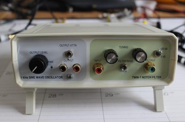
(above is the new third and updated generation. Twin-T on top, below it the Victor 1KHz reference oscillator, sitting on top of the heavily modified EM-U 0202 USB "sound card")
I started out with a very low distortion 1KHz sine wave generator and a Twin-T filter, and put them in the same enclosure.
This is the old and first instrument.
The low distortion sine wave generator is to feed the DUT, and at the output, use a filter to supress the sine wave again. What is left should be the distortion created by the DUT and some additional noise.
What was left was to design a precise filter, the required power supply and the box to put it all in to.
In addition, I needed an external sound card interface that is used as a digitizing front-end for the PC-based FFT analyzer.
I described this project on a diyaudio forum where much more information can be found about the oscillator, and the filter I used : http://www.diyaudio.com/forums/equipment-tools/252751-simpel-1-2-diy-1khz-distortion-analysis-tool.html
When I picked-up my electronics hobby again after I retired (early), this was one of the very first projects while learning the "trade" again. I wanted this tool because at the time, I was designing and building battery operated headphone amplifiers to be used on a plane.

The low distortion sine wave generator is to feed the DUT, and at the output, use a filter to supress the sine wave again. What is left should be the distortion created by the DUT and some additional noise.
The components
As it turns out, designing a very low distortion since wave generator is not that easy. Luckily I found a unit that is excellent for a reasonable price. It is called the Mickevich (the designer) Ultra Low Distortion (<0.00001%) 1 KHz Sine Wave Generator.What was left was to design a precise filter, the required power supply and the box to put it all in to.
In addition, I needed an external sound card interface that is used as a digitizing front-end for the PC-based FFT analyzer.
I described this project on a diyaudio forum where much more information can be found about the oscillator, and the filter I used : http://www.diyaudio.com/forums/equipment-tools/252751-simpel-1-2-diy-1khz-distortion-analysis-tool.html
When I picked-up my electronics hobby again after I retired (early), this was one of the very first projects while learning the "trade" again. I wanted this tool because at the time, I was designing and building battery operated headphone amplifiers to be used on a plane.
In 2022, I decided to describe the unit here in more detail, so I'm not depending on the diyaudio Forum. I also decided it was time to design a PCB and use better components for the filter, as they were recommended on the Forum.
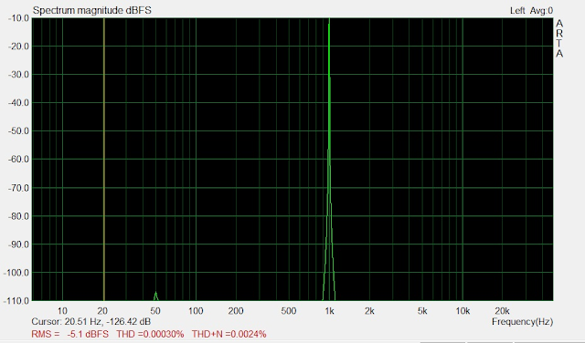
 The results for this little board are stunningly good. Here it is measured with non-professional equipment and that shows only 0.0003% THD and 0.0024% THD+N. The actual specifications are even better with second harmonic at -136 dB (0.15 ppm) and third harmonics so low it cannot be measured (< -140 dB).
Here is the modified filter circuit based on the original design:
.png)


Basically the same circuit, just some different resistor values and changed Opamps.


Here is the completed unit after the upgrade.


I selected R21 for low value 270 Ohm (about 265), and that sets the output at 34.95V. Close enough and within the specification of +/- 0.5V.

With the supply powering the Twin-T, there is a current draw on the batteries of just below 35mA. The positive rail measures +14.77V and the negative rail -14.98V. Close enough. After testing the supply for a longer period, I decided to add a small heat sink for the LM317, it got a little warmer than I wanted.

I checked both the notch filter and the oscillator with the new power supplies, and both work fine.

No mains hum and very little noise. Without the noise, however, the 2nd and 3rd harmonics now really stand out. When you look at the numbers though, 0.000051% for the 2nd and 0.000094% is outstanding.


There are added harmonics that I think are from the cables, the Twin-T input circuitry and the Twin-T output Opamp, but otherwise no mains hum and very little noise.

With a little bit tweaking and tuning, and holding my breath, I was able to get -90dBV for a moment, but by the time I took the screenshot, it already moved back up to -85dBV, staying there. Very respectable I think.

Enjoy!
paulv
The Ultra Low Distortion Oscillator
In order to make good measurments you need to have a very low distortion sine wave oscillator. I found the Victor Mickevics design and purchased one for 1 KHz.
Look for details of an improved version here: Info

Victor uses a novel application of the traditional JFET-based AGC design with a deceivingly simple but oh so clever detection, rectification circuit with standard parts to get astounding results.


Unfortunately, it seems Victor is no longer active and selling them on eBay, but you can still contact him by email and ask for his products.
The Twin-T Notch Filter
The Twin-T notch filter is based on a simplified design from Dick Moore (richiem) here are the details
I tailored his design for just a single 1 KHz operation.
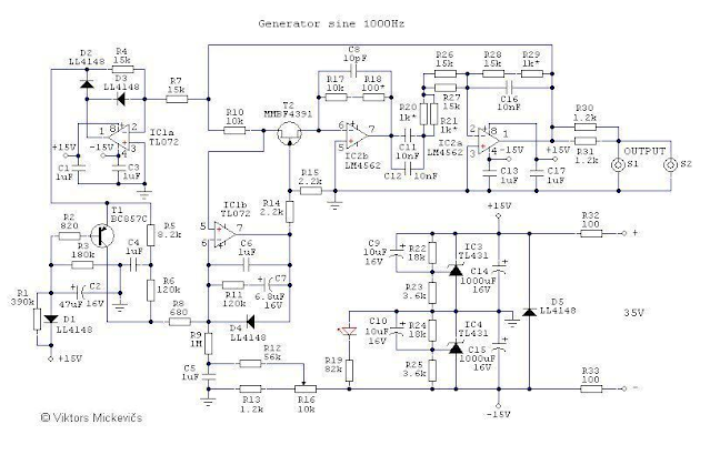
Here are the schematics that I put together for the combined instrument:
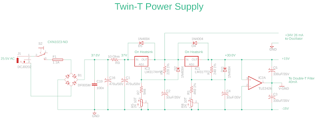
The power supply
The sine wave oscillator needs about 35VDC or a little higher, to create a +/- 15V.
The Twin-T also needs +/- 15V, but I didn't want to use the supply already on the oscillator. I did not want to disturb it.

This supply feeds the 1KHz oscillator with about 34VDC and the Twin-T notch filter with a balanced +/- 15V supply.
As I typically do, I use a separate AC transformer outside of the box, to avoid mains hum etc. When I was winter birding in Texas, I purchased a Rainbird 24VAC wall-wart transformer, alas that was only for 115V.
Back in Europe, I use a 12-0-12VAC transformer for several projects, so I used the 24VAC to feed the power supply.
Because Victor's oscillator needs 35VDC, I could use a full bridge rectifier and an LM317 and keep things cool, rather than using a doubler and deal with 70VDC as input to the LM317. They will get hot, causing temperature related drifts to the oscillator. I also did not want to "steal" the +/- 15V coming from Victor's oscillator to feed the notch filter, so I added it's own supply. To create just enough headroom for the first LM317, I adjusted the output going to the oscillator to 34V, instead of 35V.
The second LM317 is used to supply 30VDC, that is split into +/- 15V.
Twin-T Notch filter
Here is the modified filter circuit based on the original design:
.png)
I used two (cheap) 1K 10-T pots for the filter, and shunted them with 1K. This will still leave them linear enough. Even with this shunt, the adjustment is still a little too coarse to my liking.
I use R11 and R15 (rather than 10T trim pots) to set the filter notch about in the middle of the 10T filter pots.
To get the filter as accurate as possible, I purchased 8 good 10nF caps, and sorted them by value to get the optimum balance of the filter. The measured values are in the schematic. At the time I used a cheap Arduino based capacitance meter, which turned out to be less precise.
Enclosure:
Because I also wanted a nice enclosure, and not very expensive, I used a plastic one that only set me back $27. I needed to shield the inside and did that the easy way by using copper foil (look for guitar hum materials) and made two boxes out of some circuit board material. So far this seems to be adequate.Pictures of the instrument


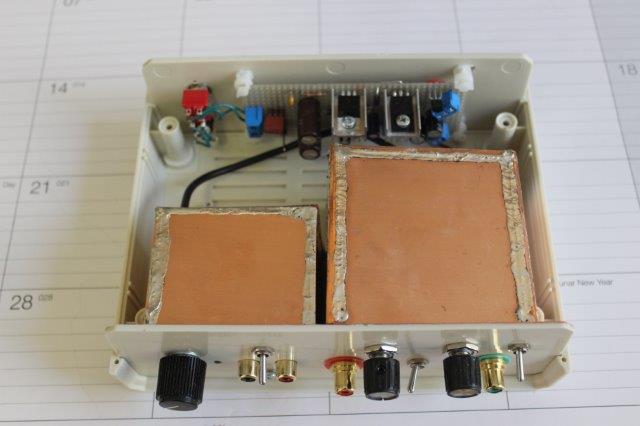


After I was done and started to test things, I added an additional toggle switch to the instrument with an input attenuator.
Improvements
Based on inputs on the Audio Forum, I learned that I can improve the notch filter some more by using better filter capacitors, the special audio film kind, and by using a better Opamp for IC1 (an AD797 or an LME49990). I now have the capacitors and the AD797 in stock.
Since then, I also purchased a higher precision capacitance meter, the Juntex LC-200A. A very good meter for the price. I can do a much better job matching the values. I should update the filter with the better tuned filter capacitors, and change the OpAmp.
UPDATE:
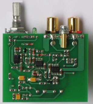
So in 2022, I decided to pick-up where I left and upgrade the Twin-T Notch filter. Now that I'm a lot more experienced with PCB design, I created a new schematic and a layout.
Here is the updated schematic:
I used the Eagle to KiCad import system to use the original DipTrace schematics but what a mess that creates when you want to make changes and add layouts/components etc. I ended-up redoing the schematic from scratch to get it clean, and produce a layout. Because I'm starting with better capacitors for the filter, I re-calculated the resistor values accordingly. They now follow the theoretical values.
The Opamps will go in gold plated DIL-8 sockets so I can easily replace them.


Note that there is no more room for the PCB-made box.
After powering it on and letting it warm up, I had to tweak some resistor values (R4, R5, R8, R9 and maybe R13) again to get the trimmer and the two potmeters roughly in the middle of the range to have an even spread either way of the sweet spot. The values are in the schematic above. With these new values, the trimmer has a good range, and the two pots are tuned to be in the middle of the range.
Adjusting them with these changes works great, I'm happy.
The PCB can be ordered from your favourite supplier.
The Gerbers are on the Github : https://github.com/paulvee/Twin-T
Significant Upgrade [May 2025]
We're now in 2025, and I'm working on a DIY rebuild of the Tektronix SG505 oscillator as a fun and learning project, described here. While doing that, I had a need for the above instrument/functionality, but while working at ppm level harmonic distortion, I found that this setup is not adequate. There is way too much hum and noise for me to investigate the 2nd and 3rd harmonics in detail, so I need to upgrade this kit.
This time, I'm going to put both instruments in their own metal enclosure, with isolated outputs and power them with 9V batteries to eliminate mains related hum and reduce noise.
The 1KHz oscillator
The oscillator needs 35V +/-0.5V so I'm going to use 5 each of the 9V cells, and use an LM317AHV to create the 35V. With 5 cells I have enough head-room to allow the cells to drain before I need to recharge them again.
I selected R21 for low value 270 Ohm (about 265), and that sets the output at 34.95V. Close enough and within the specification of +/- 0.5V.
Using the trend facility of my SDM3065X shows that after the startup, the voltage stays within a few micro-Volt, with the oscillator at maximum output, and terminated with 600 Ohm. So far so good.
The Twin-T Notch Filter
The Twin-T can be powered by the same 5-cell battery front-end circuit, followed by a copy of the Viktor Michevics shunt regulator, as is used on his oscillator PCB. If it works for him, it will also work for me. A shunt regulator adds another level of isolation from the power input, compared to a series regulator or transistor. The required current for the Twin-T is with 25mA about the same.
With the supply powering the Twin-T, there is a current draw on the batteries of just below 35mA. The positive rail measures +14.77V and the negative rail -14.98V. Close enough. After testing the supply for a longer period, I decided to add a small heat sink for the LM317, it got a little warmer than I wanted.
I eliminated the attenuator at the input of the notch filter, and optionally could used the switch now to select a high Z input, or a 600 Ohm terminated input. Any required signal attenuation will be implemented on the generator side, where it more belongs.
Why an impedance of 600 Ohm? That survived a relic standard stemming from the old telegraph lines on poles, mostly strung along the US rail roads. It had to do with measuring the repeater transformers that were used before they switched to active amplifiers. That same standard was later used for professional audio equipment for checking the long (balanced) cables for microphones etc. on stages and in studios. The 600 Ohm standard is still used as a reference point for measuring audio levels in dBm (Decibel milli-Watts).
I checked both the notch filter and the oscillator with the new power supplies, and both work fine.
The Victor oscillator is now in it's new all-metal home and is fed by the battery supply.
It's a lot happier now...
No mains hum and very little noise. Without the noise, however, the 2nd and 3rd harmonics now really stand out. When you look at the numbers though, 0.000051% for the 2nd and 0.000094% is outstanding.
Twin-T notch filter has also moved to the new all-metal home.
The board in the top is the shunt power supply.
Here is the Victor oscillator as the input with the pass-through setting.
There are added harmonics that I think are from the cables, the Twin-T input circuitry and the Twin-T output Opamp, but otherwise no mains hum and very little noise.
Housing mission accomplished!
Here is the Victor oscillator with the tuned Twin T:
With a little bit tweaking and tuning, and holding my breath, I was able to get -90dBV for a moment, but by the time I took the screenshot, it already moved back up to -85dBV, staying there. Very respectable I think.
Looking at the 2nd harmonic, that was measured above with only the oscillator to be -97.6 dBV, and now with the Twin-T at -51.6 dBV. When you add in the -85,6 dBV, you get to a -137dBV result. There is no 3rd harmonic and the others are barely visible. I think this is astoundingly good, but we knew that already, and this is Victor's first or second generation, he is now at V5 or V6 I think (he doesn't show dates or version numbers on the schematics).
Stay tuned for possible updates and maybe more measurements...
Enjoy!
paulv
If you like what you see, please support me by buying me a coffee: https://www.buymeacoffee.com/M9ouLVXBdw
5 comments:
Hello, in the text of the calibration of the new version of the filter, it says to adjust R17, I think it should say R12, and the paired capacitors C3, C4, C5 and C6, is that correct?
No, not really. The idea is that it's easier to adjust the resistors to get the adjustments roughly in the middle and leave the capacitors alone. I have updated the tweaking a bit in the Blog.
You have too much noise because the resistors are still too high into the rejector.
By dividing them by 10 and multiplying capacitors by ten, you could gain up too 10dB in S/N.
The same applies to the oscillator, but within the limits of the output current. Here, you'll have to experiment.
Thank you for the comment Charles.
Hello, Paul,
One more thing. The feedback from the bottom of the T-filter can introduce distortion and even its own noise. Perhaps (perhaps) it would be better to use a second- or 3rd-order low-high filter with a sufficiently high Q to compensate for the 9.5 dB loss on H2? This would also improve overall rejection by 12 or 18dB...
Charles
Post a Comment