Show by Label

Showing posts sorted by relevance for query fft. Sort by date Show all posts

Saturday, October 14, 2017

Setting up an FFT Measurement System


In this post I'll describe how I use a number of components/instruments to create a system that you can use to measure harmonic distortion and noise by using FFT's. This system can be configured in several ways to verify and measure the distortion of amplifiers, sine wave generators, power supplies etc.

Here is the complete set of instruments that make up the analyzer.
From top to bottom, the modified E-MU 0202 USB Sound "Card" digitizing interface to the PC, the "Pete Millett" Sound "Card" Interface, and on the bottom the combined "pure" Victor Mickevic 1 KHz sine wave oscillator and an active 1 KHz Twin-T notch filter.


First a little overview

To measure the performance (here the amount of distortion generated or added) of a black-box system (the Device Under Test - DUT), a very clean and low distortion sine wave (the fundamental) is used to stimulate the DUT, while the output is sampled. The output signal is stripped from the fundamental sine wave by means of a sharp filter, and the remaining residual, the combined noise and distortion is fed to an FFT system that can show the results.

Following is a picture of the setup needed to measure the Total Harmonics Distortion (THD) and the THD plus noise (THD+N) from a DUT.


This is a setup that can be used to measure sine wave generators, or to verify the Sound Card interface to the PC and the FFT software.

A high quality low distortion 1KHz sine wave is fed to the DUT, here symbolized as an amplifier. The output signal from the DUT is fed to the Soundcard Interface and is probably attenuated. This interface protects the delicate and sensitive inputs of the other intruments in the chain, like the T-filter and the USB Sound Card, and also facilitates making a few measurements. The resulting output is then fed to an (active or passive) Twin-T filter which removes the 1KHz fundamental. The residual (everything added by the DUT to the pure sine wave) is then fed back into the Soundcard Interface and then going to the USB Sound Card Interface, here a simple SD-AUD20040, where it is digitized and sent to the PC over a USB link. On the PC/Laptop, a software application like AudioTester, is used to show the residual (and noise) by means of an FFT.

This same setup can also be used to measure the noise performance of a power supply. In that case, the power supply output is first stripped from the DC component by using a capacitor (not shown), and then fed to the Sound Card Interface, and from there to the USB Sound Card for digitizing and on to the PC and the AudioTester FFT software.

If you want to measure the quality of sine wave generators or verify the components in the link, you can also use the following much simpler setup.


How you inter-connect the various instruments depends on what they offer. In this example, the output of the sine wave generator is fed directly to the Twin-T filter and the residual is digitized by the USB Sound Card. The Sound Card Interface is not needed, because the input levels can be set low enough, althoug you need to be carefull or use attenuation adapters.


The instruments that are used in the chain

In an earlier post on this Blog, I already described how I put the the "vicnic", a very high quality sine wave generator, and an active Twin-T filter in an enclosure.
On the left is the 1KHz sine wave oscillator with a dual output connector. One the right is the Twin-T notch filter, optimized for a 1KHz sine wave.


This instrument is described here:  simple but precise 1khz distortion system

The sound card interface

I also used a DIY Sound Card Interface, to attenuate (high) signals coming from the DUT, which would otherwise destroy the input of the USB Sound Card, or the other measurement components. The output from the Interface then goes to the Twin-T filter and then to an actual USB Sound Card (to digitize the analog signal) connected to a PC. The digitized output of the Sound Card is used by the AudioTester software running on the PC to show the results, typically by showing a pseudo Spectrum Analyzer  FFT diagram.


The Sound Card Interface above is another DIY project based on a design from Pete Millett and described here

The USB sound card interface

A USB sound card is used to digitize an analog signal (typically music) so it can be send to a PC for prossesing. It's still called a sound "card" interface because in earlier years this was actually an add-on (or more precise, an add-in) board that plugged-in to a PC slot. With Laptops, that option is no longer possible so a separate instrument with typically a USB interface has to be used instead. 

The same instrument can be used in our chain to digitize the resulting signals for further processing on the PC/Laptop.

During my first baby steps in putting this system together and collecting some experience, I used this inexpensive (around 25 Euros) USB Sound Card Interface:


It worked OK as you can see in the posts I mentioned earlier, but I was not very impressed with the results. It needed further tweaking, adjusting and modifying. After getting it all working and playing with the chain of intruments and making some measurements, I moved on to other projects. So for a few years, I really didn't need this setup so didn't spend any more time on it.

New technology and upgrades broke the chain

When I recently wanted to profile my DIY Tek SG502 rebuild, I put the system together again and quickly made some changes to the inter-connect cabling that makes the connections between the units easier.

However, problems showed-up right away that I had not seen before. It was probably caused partially because in the meantime, I switched to a newer and different Laptop and I also upgraded to W10. I could also very well have done something wrong during some of my experiments, because I suspect that something in the USB Sound Card box could have be damaged because it now shows a lot more harmonic distortion then I remember having seen before.

At first I was mystified to the cause, and could not put my finger on it. I now attribute it to a combination of my W10 Laptop, the W10 sound drivers, the W10 drivers for the USB Sound Card, plus something wrong with the drivers of the AudioTester software, because it is now crashing all the time.

Fault finding...

There were way too many variables in play so I started to address them one by one.

When I used my FY6600 DDS Function Generator, it showed THD+noise performance that looked pretty good and only a little worse than the specifications. 
My unprofiled and just finished Tek SG502 was also just outside the distortion specifications, but that was to be expected. So far so good. 
However, the ultra pure 1KHz sine wave generator designed by Victor Vickenich (vicnic) showed results that were only a little bit better than the other two, so initially I started to suspect the 1 KHz reference. 

To address my first suspect, I got in contact with Victor because I suspected a problem that I must have created with his reference. With his patient and excellent help, we found out by making some measurements on the oscillator itself, that the problem was not due to his sine wave generator. Of course it wouldn't.

I then focussed my attention to the PC software side. I have a license for the AudioTester software, but I was not happy with the overall driver situation after I switched to W10 and I also had problems with the calibration. To eliminate that aspect, I tried another software package, called ARTA. I selected this, because there are many references on the web and many examples of measurements made using Victor's oscillator in combination with the ARTA software, so I could start to compare. However, it still did not improve on the root cause of the problem I was having, the excessive harmonic distortion on Victor's oscillator. Have a look here...


That simply looks terrible! It has to be something else in the chain...


A better USB Sound Card

It was now time to take the next step, and invest in a better USB Sound Card. After quite a bit of research, I purchased a (brand new) ASUS Xonar U7 from Amazon. To my utter dismay, I found out that the CD that came with the unit did not have W10 drivers. Also online was nothing to be found. C'mon ASUS, we're in the middle of 2017, and you have not updated the CD yet? Obviously, that did not give me a lot of confidence. Making a few measurements did not improve the situation much, so I returned the unit the next day.

Time for a reset. I realized that I lacked the knowledge to get to the bottom of this issue, so I had to learn a lot more first of all. I literally spend a few weeks going through all kinds of Forums and Blogs to see what other people were using, and to learn more about the overall system and the components in the chain in much more detail.

Eventually, after going through many blogs and forum's, I found that there were a number of USB Sound Cards that stood out. The majority were from the same company, the E-MU 0202 and the E-MU 0404 and also a few others. The good news was that they were available "as used" on eBay now and then for reasonable prices.
I decided to try to score one of these and after some miss-hits, I scored a used E-MU 0202.


Modifying the E-MU 0202

After I scored the bid for an E-MU 0202, we were out of the country for 7 weeks (Winter Birding), so the unit would arrive but I would not get my dirty little hands on it. This gave me the time to do some more investigations, so I started to study more about the 0202. 

The ultra-pure 1KHz sine wave generator I have was designed by Victor Vickenich (vicnic), and to my delight, I found that he also published a couple of modifications to his own E-MU 0202 Sound Card, with lots of pictures together with the FFT results using the same 1KHz source. With the modifications to the 0202, Victor was able to get incredibly good results. 

That was going to be my reference now.

During my investigations, I also learned that the schematics for the 0202 are very similar to the 0404, although in a different layout and with several value changes and part numbering changes. Schematics for the 0404 are available, but I did not find good ones for the 0202. The various sources of 0202 schematics I found on the Web had errors, or were incomplete.

Since I had nothing else to do at the moment, I took the time to capture all information I could find in my schematic capture program (DipTrace), so I would have a record of the original status, and could put a description together for the modifications Victor did.

Based on the various sources and photographs of the PCB, here is the resulting schematic I was able to put together for the E-MU 0202 "B" channel input to the ADC, the well known AK5385AVF. That chip provides 24-bit resolution at a 192KHz sampling rate and has a 114dB dynamic range.
Here is the data sheet from DigiKey.

E-MU 0202 Front-End Schematic Diagram Channel B 


And here is the slightly more complex "A" channel:

E-MU 0202 Front-End Schematic Diagram Channel A


For the time being, I left out all power related parts. I may add them when needed, because at the time, I was considering adding an external separate power input, instead of using the (typically very noisy) USB 5V coming from the PC. That's a potential project for later.

My plan was that as soon as I got home and could start to work on my unit, I would start with the modifications that Victor made to his 0202. He eliminated much of the front-end of the unit and only used the "B" channel. He also uses an attenuation of his own, so there was no need for the input section. 

I will be using my Sound Card Interface only for this application, so this is no limitation for me either. Cutting that input section out of the loop saves a number of dB's in noise, and turns the Sound Card (more accurately a digitizer) more into a tailored measurement instrument.

Modifying my E-MU 0202

The EMU0202 I scored on fleabay was supposed to be working, but that was not true. The output amplifier did not work. I could not find the error, but I really didn't care. I wanted the digitizing front-end, so I applied the same modifications Victor published and did on his 0202.

Here are the two links to Victor's modifications and measurement results, they start with post #171 on page 9:
Victor's modifications and results

Scroll to page 10 and post #184 to get to his contribution with the photographs and the modifications. 
Note that a little below this post is another one from him with a correction to the value of R46, which needs to be 6K8. This is in post #187.

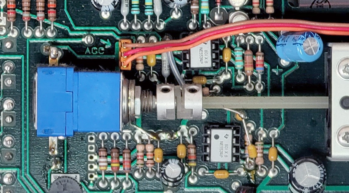
Below is the schematic information I put together for his modifications to the "B" channel, and highlighted the parts to be removed to isolate the front-end components to ADC input.


The volume control potmeter is removed to make place for an RCA or BNC connector on the front panel. I used a BNC connector myself.
The two removed series resistors, R54 and R32, both 1K4, will isolate the front-end input from the drivers for the ADC. The two resistors that are used to create the dynamic zero balance, R35 and R41 need to be removed too.

Following are the value changes and the new additions to form the new input circuit to the ADC.


The RCA or BNC connector can be mounted on the front panel in the hole of the R-Hi-Z/Line potmeter. I had a BNC connecter that fitted perfectly. After that, the input series resistor, the capacitor and the input Z resistor can be mounted Manhattan style. Note that Victor mentioned that this resistor can be tweaked in value to remove artifacts. I kept mine to 220K.

Three feed-back resistors change in value.
R28 : replace the 1K value to 6K8.
R46 : replace the 1K value to 1K5
R34 goes from 1M to 1K. (Victor used the original removed 1K resistor from R28 and simply soldered that resistor on top of R34 with the 1M value.)

Finally, the connection from the output of U6-B to the input of U6-A can be created by soldering the second removed 1K4 resistor, (the originals are too small, I used a new 1K5 0603) "Tomb Stone" and with a small wire to the input of U6-A. His detailed photographs show the way.

The results are stunning!

Connecting his reference oscillator to my now modified EMU0202 shows rather stunning results I think THD = 0.00096%,  noise at -120dB. Wow!


So now my modified EMU0202 digitizing front-end together with Victor's high quality oscillator, is a perfect reference combination for my distortion measurement applications.

As you can see from the picture below, I used a BNC as the input connector.


Here is a screenshot of the modified EMU0202 with my analog DIY Tektronix SG502:


The measured THD of 0.026% of my DIY re-build is actually better than the Tektronix specification of 0.035%. Not bad at all!

And here is the result from my digital FeelTech FY6600-30 Dual Channel Function/Arbitrary Waveform Generator:


So with the described changes to my setup I finally solved the issues I had in the chain. 

Next step will be to add in the Pete Miller Soundcard Interface and do some more measurements.

It may take a while, I have a few other projects I'm working on, but stay tuned for more...

Enjoy!

Monday, November 3, 2025

The DIY SG505 mains power supply

This post will detail the mains related portion of the SG505 generator. I decided to split the whole power section in two, the quiet parts stay with the main generator, and the mains related and otherwise inherently noisier parts will go into another enclosure, all by themselves.

Think of it as a dedicated substitute for the TM5XX mainframe the original SG505 would have as its home.

After a few revisions, this is the final version of the supply, Version 4. (I'm showing it here so it shows-up on the title page of the Blog post)


The V3 Mains Power Supply

In an earlier version, the power supply was on the main SG505 generator board. This circuit  is inherently noisy and will no longer be in the same enclosure as the generator. 

This is the schematic of the new version I'm now working from. There are not too many changes, but I added ferrite coils in between the larger reservoir caps, and I used a common mode coil at the output. I also added a few more capacitors to quiet the thing down as much as possible.


The dimensions of the board are such that it can go in any kind of enclosure, and mounted on studs through the 4 mounting holes.


Discovered an issue

After trying the new setup, I discovered that I made a mistake...


A wimpy transformer

With the generator working, I started on the counter section. However, when I flipped the power switch, the generator almost stopped working, the output dropped significantly. To make a long and embarrassing story short, I misjudged the amount of power that the counter circuit draws on the supply. I measured it at 120mA, and was under the impression that with the 50mA for the generator I was within the power budget of the transformer. We're not because there is a significant voltage drop of the raw supply, dropping the headroom for the 40V regulator, and then also for the shunt regulators.

Here is the culprit, the VPP28-180, a 2x14VAC @ 180mA. It's not beefy enough. I had that one in my stock so used it. I should have know better, and I should have tested it better.

A new transformer will require a turn of the board, but I'll wait to be sure. Extra sure. This time.


To continue with the rest of the assembly and testing, I took off the 12V regulator parts from the main board, so they would not interfere and I could supply an external 12V to power the counter circuit.

The rest of the generator worked fine, so I could spend some more time on the power supply fixes that resulted in a board turn and a version 4.


Power Supply V4

To counter the lost head room when the current goes up, I tried a 15-0-15VAC transformer that I have in stock and is much beefier with 800mA. I used one of the spare V3 PCB's to build-up a new version, and also made some changes, reflected in the new schematic.

I used larger filter capacitors with 2200uF/63V, the only ones that I have with this voltage. The 1000uF/50V that I used before is a little tricky now with the higher input voltage. I ordered 1000uF/63V, and also 3300uF/63V to give them a try later. 

The second 75mA fuse is gone. The larger load and the filter capacitors cause an in-rush current that is blowing the fuse. I now use a 500mA PTC instead while testing, it will be lowered to 200mA after my testing.

When using the new 30VAC transformer, I measure the ripple at a load current of 200mA (using my Dynamic Load), and I only see 400mV, the raw voltage is 42.5V, which is not enough head-room for the regulator to provide 40V. 

When I increase the current to 240mA, the voltage regulator drops out of regulation.

At a load of 160mA, the raw voltage is 43.2V and this is the expected current draw of the instrument as far as I can tell. I need to measure that again, but I need to put the parts that I removed from the 12V circuit back on the main board in to do that. That requires a disassembly of the instrument again, and is next on my list, but not today.

I added the 12V regulator components on the main board and started testing again. The generator works fine when the counter is off, but when I switch it on, the positive 16.5V supply drops, this is due to the 40V dropping a bit, and that is because the raw unregulated voltage is dropping too much for the 40V regulator to continue to provide a steady 40V. That was to be expected because there is not enough headroom. 

The result of this investigation is that even a 2x15VAC is not enough, even though the transformer should have plenty of power.

Here is what I measured at the DC unregulated side with that supply:

Open : 49V, Generator 46V, Generator + Counter 42.7V: not enough, another wimpy transformer.

Using a beefier version

Next try is with a VPP36-560, a 2x18VAC transformer, another one that I have in stock. It was a left over from the Curve Tracer project. I don't need the 560mA it provides, but this transformer type is also available in a 280VA version.

When I measured this transformer, it showed these results:

Open : 60V, Generator 56V, Generator + Counter 51V.
The ripple is still 200mVp-p but we have plenty of headroom now.

With the unregulated input this high, the 40V regulator must now have a good heatsink, which was not required with the lower voltages. It's easy to create some room on the PCB to add one though.

With this transformer, there is no voltage drop anymore, and the other good news is that the generator continues to function very well with the counter on or off.

New power supply, counter off:


And below is with the counter on.
 
Note that this FFT is not as nice as the previous one, it has some hum and I had to readjust the H2 but this time could not make it disappear. I also found that the Vernier adjustment changes the H2 distortion level a bit. Looking at the circuit, that seems to make sense as it is in the feed-back loop of U1 where also the AGC is used as a summing-input. I'm speculating that the hum could be the result of the 40V regulator needing to work so much harder due to the significantly higher raw input voltage.


There is virtually no change in the noise floor (-128dBV and also in the harmonics). The 12V section is now quiet enough although for very clean measurements, you could switch it off, just in case.

THD is now 0.00033%. 

Adding a pre-regulator

With the extra head-room that the 2x18V transformer provides, I can now also implement a pre-tracking regulator. Because the job is then split in two, with one working on the line regulation, and the other on regulating the voltage output. The load is shared, so I can use two much smaller heatsinks.

Besides, the split will also create more separation between the mains related hum and the output voltage. The U1 pre-regulator provides about a 5V head-room for the U2 voltage regulator. Only 4 additional parts are needed for this pre-reg circuit.

Below is the text-book (from the LM317 datasheet) implementation of the pre-regulator, or tracking regulator.


(this is not the final version, have a look at the Github site (link below) for the most current information)

With the Manhattan style modification to try it out, and the long flying leads to the transformer, I can't see the benefits in the FFT, but my hope is that it will, once everything is on a proper PCB. 


I can even reduce the size of the heatsinks you see above, the regulators are not getting hot.

As soon as the ordered filter capacitors come in, I can try the 1000uF versions and see if they are adequate.

In the mean-time, I'm working on the new layout for the power supply.


The layout has provisions for the VPP36-560 transformer (11,62 Euro's at DigiKey) the one I already have and will use, and the smaller VPP36-280 (8,62 Euro's at DigiKey) which should be sufficient.

I also measured the supply with the 2x1000uF/63V and also the 2x 2200uF/63V for the main filter capacitors C6 and C7. The ripple voltage measured across C7 with the 1000uF was 320mV and with the 2200uF 200mV. Both values are adequate but the PCB will support both types.

Happy with these results, I uploaded the updated power supply V4 and the updated front panel Gerber files to PCBWay for production under our sponsoring arrangement. (even though I screwed-up twice, nice of them)

It will usually take about a week for them to arrive.


Final results

The boards from PCBWay arrived in the usual very good quality and I build-up one of them. Check them out for your own projects: https://www.pcbway.com/

Everything worked flawlessly, so I adjusted the output to 42.00V and connected the generator board. After a few minutes, while calibrating the voltages, the power dropped to zero. It turned out that I used a 100mA PTC for F2, and that is getting too warm and cuts out. I'm now using a 200mA PTC that I planned to use earlier, and that works fine.

I calibrated the output voltage again but now measuring the Vreg on the generator board, to account for a few 100mV power losses, and then proceeded to calibrate the +17V and the -17V. 

I could not adjust the +17, it stopped at about 16.4V, however, the -17V worked fine. This is due to a Vreg that is a little too low for the balancing to work, so I raised the Vreg voltage to 43V and all was well. To add a little bit more headroom, I'm now setting Vreg to 44.00V.

The heat sink I selected for the main voltage regulator (U2) is a tad too small, because the device gets a little warmer that I hoped for. I can still touch the tab without burning my finger so there is no real issue, but still. The U1 pre-regulator is only warm to the touch so fine.


Below is the now completed enclosure for the power supply.


The front panel is the back panel from the SG502 that I'm using here as the front panel.


And below is the setup of my instrument bench. 

The top shelf has the actual instruments. From left to right: the DC Dynamic Load, the SG505, my frequency counter, and the GPSDO on top of the master clock, the rest is out of sight) BTW, these are all instruments that are listed on my Blog. Below that shelf is room for the supporting stuff, like the power supplies.


This concludes this project for the time being.

Here is the overall project Github with all the design files: 
https://github.com/paulvee/DIY-Rebuild-of-the-SG505

Here is the Shared Project listing on the PCBWay website:
Shared Project DIY SG505 Power Supply


Thursday, September 25, 2025

DIY rebuild of the Tek SG505 Part 3 (final)

This Blog post will detail the third stage of my project to rebuild the Tektronix SG505 instrument.


Here is the link to the post describing the second version of the design: 

https://www.paulvdiyblogs.net/2025/08/diy-rebuild-of-tek-sg505-instrument.html

Here is the first post about this project:

https://www.paulvdiyblogs.net/2025/03/diy-build-of-tek-sg505.html


The reason for the third revision

After the investigations of the second version, I wanted to separate the Power Supply from the Generator in the same enclosure. I also wanted to put the Generator circuits into a full metal enclosure to make the output of the generator as clean as possible and as a minimum, remove the mains hum.


After a very long search, this is the only enclosure I could find that has the required height and width for the front panel layout. It is a ProMa 130 0044 and is also available from Amazon. The outside dimensions are 165x110x80. I would have liked a black enclosure, but alas I couldn't find one. There is one available from ProMa though, with part number 130 0045. I can always spray paint it black myself if I develop the urge. The current Front Panel design will need some modifications and will replace the aluminum panel. The generator PCB will slide in a slot close to the bottom. Unfortunately, the dimensions are a little different so I can't use the current PCB in this enclosure, not even to try it out. 

This all means a new PCB for the Generator, for the Power Supply and for the Front Panel.


Splitting the Power Supply

There will be a separation of the noisy mains related parts of the circuit, that need to go outside of the enclosure for the generator. In essence, it means that the transformer, the bridge rectifier, the main capacitor reservoirs and the 40V regulator need to be on a separate PCB that will be housed outside of the generator.

This part of the project will be described in a dedicated post here:
https://www.paulvdiyblogs.net/2025/11/the-diy-sg505-mains-power-supply.html

The shunt supplies for the +/-16V rails can move to the main generator, and also the 12V supply can move to the main board. They are quiet and will have no negative effect on the generator. I hope. It also makes the interface from the Power Supply enclosure simple, because I will only need to use two wires for the 40V supply that feeds the other three rails.

The circuit after the transformer and the bridge will get some more filtering to avoid mains related noise getting into the generator.


The Power Rails on the Generator PCB

These three rails are very quiet by themselves and can now move to the generator PCB.


(this is not the final version, have a look at the Github site (link below) for the most current information)

No major changes from the previous design, I just added a few extra capacitors and ferrite beads to the power input lines. This may still change a little based on the new layout.

Just when I was about to order the PCB from PCBWay, I decided to skip the idea of using a heat sink for the LM317, because it will still get too hot and raise the temperature in the box. It will now be mounted isolated to the side of the aluminum enclosure.

The Generator circuits

The other circuits stay the same, will just get a revised layout and incorporate the three power rails and needs to fit in the new enclosure.

I finished the new version of the generator PCB, now with the power rails on it.


This is what is ordered. On the bottom part you can see that the LM317 is now flipped around and moved closer to the edge of the board. It will be mounted isolated on the side of the enclosure to remove a considerable heat source.


The Front Panel

This is the updated front panel fitting the new enclosure.

The golden rings around the holes connect the front ground fill to the back ground fill to add an EMI shield to the inside circuits. 


The rings on the back are larger so will connect to the metal parts of the switches, connecting them to the shield. The 4 mounting holes in the corners also have exposed holes on the back and will connect the shield to the aluminum enclosure. 


The enclosure itself is not connected to earth ground but floating. I have created the possibility to connect the GND of the PCB circuits close to the output BNC to an exposed pad on the front panel. In that case, the circuit GND will be connected to earth GND when the BNC is connected to a DSO.


Building up the boards

I received the shipment with the three PCB's and I have built up the power supply by transferring most of the parts from the old board, added the additional parts and tested it. No problems.

The next step was to add the solder paste droplets to the main generator board and transfer the parts one by one from the old board. I used my heat gun to remove them and put them on the new board. When that was done, I reflow soldered the board. Because I used smaller solder paste droplets this time, the reflow process went a lot better, with only a few tiny solder ball bearings and a lot less of the flux gue. I did not clean the board just yet, I wanted to test the functionality first.


Discovering issues

Bad Solder joint

At first I wanted to check the voltage levels of the three power rails. The +16 was only about 9V and then dropped to 3V, the negative 16V was about 30V, the 12V was OK. Although nothing got warm, I quickly shut it off. After connecting the switches and potmeters to the connectors such that the generator could function, I applied power again and saw a welcoming sinewave, albeit with some distortion at the top half. Hmmm, partial good news. When I checked the 16V rails, I still noticed a large unbalance, and that explained the distortion. The good news is that the most complicated circuit seemed to work OK, but the most simple circuit did not, but why?

The hunt for the shunt supply imbalance turned out to become more and more strange. To a point where I started to remove the parts from the shunt supplies one by one, but without any improvement. Using my Lab Supply instead to first power the +16.5V and the -16.5V everything worked, I then supplied the 40V supply, further up-stream and that also showed the correct currents and the system worked fine. Now really puzzled, I used another one of the spare generator boards and started to add the minimum amount of the same parts I just took from the board for the shunt regulator to make it function, which it did flawlessly. Even powering the generator from the second board showed the correct balanced voltages. I was flabbergasted. After thoroughly cleaning the board and resoldering the components back to the board in pairs, everything worked. Bad solder joint!

Wimpy transformer

I also discovered that the mains power supply had a wimpy transformer, so that also needed attention. Details are in the other post: 
https://www.paulvdiyblogs.net/2025/11/the-diy-sg505-mains-power-supply.html


Mistake on the front panel

When putting everything together, I first mounted the construction for the main potmeter and the reduction unit. It fitted perfectly, unlike with the first front panel. So, happy with that result, I added all the other switches and potmeters and proceeded to slide the board into position, when I hit a barrier.

Turns out that I made a serious measurement mistake with the position of the rotary switch for the multiplier. It was bumping to the board and also bumping to the reduction unit. Moving the hole up and left solved that issue, but it will mean another turn of the front panel.

This is how it looks now, so close...


This is the inside view of the now fully working instrument:


Mains related hum

When I did the first FFT tests, I still saw some 50Hz hum and some harmonics. When touching the metal parts of the front panel, it got sometimes worse, sometimes better. I did not have the main potmeter knob mounted, and when I touched the metal axel, the hum got worse. Connecting the Earth GND from the output BNC to the metal parts of the main potmeter and reduction unit with a wire did not do anything, but connecting it to the common GND of the main board reduced the hum dramatically.

It turned out that the mounting holes for the main potmeter support and the reduction unit did not connect the metal parts to the common ground of the PCB. I used star washers on each support to improve that. I also added a blank ring to the layout around one more hole of the contraption to improve that going forward.


Connecting earth GND to common GND?

I intentionally connected the front panel shielding to the metal enclosure to create a Faraday cage, but I separated it from the common GND of the board.  

In my current setup, with the USB connected EMU0202, however, that produced too much unwanted mains related hum. 

I already added a solder tab on the back of the front panel as an option to make the connection possible. When I soldered a wire to it, and connected the other end to a solder lug I added to one of the supports for the main potmeter to connect the two GND's together, it solved the hum issue completely. But now the instrument is earth grounded through the EMU to the laptop, which by the USB-C cable to the power supply is connected to earth GND.

The other possible connection for the instrument to get earth GND connected is through a BNC cable to a CRT or DSO and that will connect it to earth GND as well.

The original SG505 has a switch to connect the common GND to earth GND. If you also want to have the option to separate or connect the enclosure from earth GND, you could add a toggle switch to the back of the unit, or a sliding switch on the side. I'm undecided at this moment, but it's easy to add afterwards.


Result after the fixes

After all these mishaps and corrections, I wanted to share the first FFT from the generator, hot of the press. Note that I was able to quickly trim the second Harmonic visually into oblivion (0.00002%).


Result, no hum, no noise. 

Unfortunately, with H2 visually gone, H3 is now sticking out, but the rest of the harmonics are virtually invisible. 

During my testing with the updated power supply and mounting everything on the front panel a few times while fixing things, I noticed that I could no longer adjust the H2 harmonic as low as it was above. There is now also some hum visible, so when the new supply arrives, I will look at it again in more detail. 

Just for reference, my DIY version of the generator seems a bit better than the original one. Albeit using different measurement tools.


I'm almost there...

Building the final version

Happy with all these results, I uploaded the updated power supply V4 and the updated front panel to PCBWay for production. They gracefully continue to sponsor my activities, despite my screw-ups.😇

It will usually take about a week for the shipment to arrive.

I got the front panel, but made a mistake ordering the power supply board, so that will come in another week. See the dedicated Blog post for that part of the project here

In the meantime, I started working on the various BOM's, including an off-board one for the front panel parts. They, and all other information will be on my Github site that I will publish when I'm done. 

I have been using a lot of parts I already had, but needed to find parts that I could put on the BOM so others can order them. Here are some details for the off-board parts.

Output signal potmeter

One of the challenges was to find a potmeter for the output volume with a switch, that is activated at the end of the rotation. Most of the ones I found switch at the beginning, at 50 degrees according to the specifications.

I put one together with parts I had from a previous life, and that looks like this:


These potmeters come in separate segments you can take apart so you can create stereo versions, or use two different resistor values, and optionally also add a switch segment. I was able to turn the switch segment around to get the right action. To have the switching indent at the end of the range is more natural, because the switch fixes the generator output by a resistor divider just below the maximum output. This is also how the original SG505 has it. I put a potmeter in the BOM with a SPDT switch, but it will be activated in the beginning of the rotation. If you are able to find a potmeter with the switch activated at the end of the rotation, let me know in a PM so I can share it with others.

Mounting the main board

You can add all the components on the main board, but do not solder the 12V regulator in position yet. The height of the regulator to the board needs to be determined first. 

It's now time to mount the main potmeter and the reduction unit using metal brackets to fix the position of the axel in the middle of the hole of the front panel. Add a solder lug on the screw that fixes the reduction unit with the screw hole that has an exposed ring on the bottom of the PCB. The is the one closest to output on/off switch connector. Lightly tighten the screws and nuts and try the position of the whole contraption with the hole in the front panel. When you're happy, see if you can tighten the nuts while the PCB is still on position. If not, you need to carefully slide the PCB a few cm out of the enclosure slots such that you have access to the screws on the bottom. Fix everything and try it again.

When that is done, you should have the main board flush to the front panel, with the potmeter axel in the middle of the hole. 

To mount and fix the 12V regulator, we need to drill a 3.5mm hole in the side of the enclosure to give it a good heat sink. Position a sticker on the inside of the enclosure about in the position where the regulator will be. My hole was drilled in the middle of the third rib from the bottom. The hole should be drilled the middle of that cooling rib, because the head of the screw need to be in the center between the ribs. Position the main PCB in position, such that it will be flush with the front panel. Put the LM317 in position after you have clipped a few mm from the legs so they don't connect to the bottom. With the regulator inserted in the PCB, note the position of the hole and mark it on the sticker. Use a caliper to measure the distance from the front edge of the enclosure to where you marked the center of the hole of the LM317. Transfer that measurement to the outside and mark the position in the middle of the rib. Remove the main board and drill a 3.5mm hole in the enclosure. Grate the hole on the inside so there is no burr. Slide the main board in position again, and maneuver the hole of the LM317 to align with the hole in the enclosure. use a screw and nut to position the LM317 and solder one or all of the pins to the regulator when it is in the correct position. Remove the screw and carefully slide the main board out of the enclosure. You can now permanently solder all three pins to the main board. 

Important! When you will fully mount the regulator later, (not now) you have to use an isolation pad (mica or silicon) and a plastic isolation ring to make sure the metal pad of the LM317 is fully isolated from the enclosure, or you will have a dead short of the supply rails.

Fixing the OLED display to the front panel

Do not mount any of the other parts to the front panel yet. It allows you to handle it and the fragile display easier. 

I first used a black permanent marker to color the inside of the rectangle in the panel pitch black. Do that from the inside so you don't smear ink on the face side. 

Make sure you can power the display from the main board while positioning it so you can see where the text is, relative to the viewing area. It will be virtually impossible to position it correctly otherwise. If your main generator board is not inside the enclosure with the 12V regulator cooled by it, you have to use an external heat sink, because the regulator will get too hot otherwise.

Using glue

You can try to glue the OLED display in position to the new front panel. You need to add some glue (not instant glue) sparingly(!) so it does not flow into the visible area when you gently(!) press the two together. Add the glue on the front panel backside. Power the display so you can see what needs to be visible and position it horizontally, put it in position, and keep it there until the glue is dry enough.  I first tried that, but abandoned it.

What not to do

In my earlier glue attempt, I used a washing cloth clamp to secure the OLED display in position when letting the glue harden. We'll that seemed to have destroyed the display because it turned black. I first thought that the clamp must have pressed too hard and damaged the flexible cable connection between the glass and the PCB. I had no spares so needed to order a new display. 

Well, after the new display's arrived, none of them worked. Tongue in cheek and red faced I have to admit that it wasn't the display. While trouble shooting, I measured the SDA and CLK signals with my DSO and I measured 5V on the display PCB with my DMM, so I started on a rat race trying to find the issue. After a while searching, it turned out that the crimping of the GND wire on one side of the interconnect cable was bad and must have disconnected while I was clamping to let the glue dry. Although visually the crimping looked OK and I did not look further, but searched for other causes. Long story short, what I did wrong was that I connected the GND of my DMM to a GND pin on the main PCB, in effect bypassing the bad GND wire connection when measuring the 5V. I did the same with my DSO, but that still showed the presence of signals so I did not look further. I replaced the GND wire in the extension cable and did a better job crimping the connecter and all is well again.

In hindsight, it's probably safer to use some normal Scotch tape to keep the OLED display in position while the glue is drying. Or, don't use the glue method at all. 


Using Scotch tape

I ended up using Scotch tape to secure the display, I used electrical tape earlier but that's too flexible and the display sagged down a bit. 

In the picture below, I used another PCB on top of the front panel so I could position the OLED board better. In my case, the distance between the top of the OLED board and the top of the front panel was 20.78mm. You can easily check the horizontal adjustment that way by sliding the display horizontally into position. Because I used clamps to press the two boards together, I could rather easily adjust the vertical and horizontal position of the OLED display within the rectangle opening. To do that you have to power the OLED display from the main board so you can see where the text is.


After positioning the display with one piece of tape while positioning it, I used some more Scotch tape to finally secure it in position. Do not cover the onboard regulator with tape. I used a piece of double sided foam tape to bridge the distance to the front panel en the OLED display where the connector is. It should help with the stress put on the rather flimsy OLED board sandwich with the glass display when you plug the connector in.


It does not look very pretty, but does the job and is not permanent.


Assembling the front panel

Do not fasten the front panel to the enclosure just yet. First mount the switches with their cable harnesses already in place, with the solder ends shrink-wrapped for sturdiness. Ask me why. Mount the Vernier potmeter and the volume potmeter. Solder an about 8-10cm thick ground wire to the solder pad on the back of the front panel, with the wire going upwards. 

Mount the rotary switch into position with the connected wires on the top side, away from the main board.

Get the front panel roughly in position to the enclosure with the main board already in place. Solder the other side of the ground wire to a solder lug you should have installed on one of the mounting screws of the potmeter delay unit.  Take one of the screws that have a ground ring on the bottom so there is a solid ground connection. Check with an Ohm meter for only a few Ohms max. between the front panel exposed holes to one of the GND test pins on the main board and the outer ring of the BNC connector.

You can now connect the wire harnesses from the 0/-10dB switch to their locations. The wiggling room is very tight which is why it should be clear by now that you should not have fully mounted the front panel yet.  Then connect the output on/off switch connector. At this point, make sure the switch operation is correct, because you can still turn them 180 degrees to fix that. The other connections are not critical, so you can now mount the front panel into position with the two screws going into the bottom half of the enclosure.

You can now add the ring and nut for the BNC connector and tighten it lightly such that the main board is flush against the front panel. You should have tried this position already when you mounted the voltage regulator to the side of the enclosure such that you don't put too much force on the leads of the LM317. With the front panel mounted, you can now also mount the LM317 into position. Remember to not forget the isolation! Double check again that the metal tab is indeed isolated from the enclosure.

You can now connect all the other wire harness connectors and add the knobs into position.


Calibration procedure

Now it's time to add power and check all controls and that the switches are in the correct working position.

By now, you should have a sinewave output and the counter should show the frequency. If all the controls work correctly, it's time to let the unit warm-up for at least 15 minutes. After that, it's time to finely adjust the 44V main rail, while measuring the voltage on the main board using the +Vreg and -Vreg test points. Adjust the rail voltage with the trimmer on the main power supply board.

With that done, you can now verify the voltages of the +17V and -17V rails. They should be within 0.5V of each other and 17V +/- 100mV. If not, you can change the resistors that are setting the voltage for the TL431's. If you installed the optional trimmers, you can set both rails as close as you can to +/-17V and equal to each other.

To adjust the 2nd harmonic adjustment, you need to use an FFT to see the effect. With the unit now sufficiently warmed-up and the rails adjusted, you can trim the 2nd H trimmer for a minimum height or dB value. You probably have to use some averaging of the measurement to see it well.

Now we can calibrate the 0dB output level. Select the 0dB output level with the switch. Select the Cal position switch setting on the output potmeter. Connect the output of the generator through a 600 Ohm in-line terminator to a DMM in the AC mode. Select the 1KHz frequency on the generator, because the DMM will most likely be precise at this frequency. Adjust RV2, the 0dBm adj. trimmer for a reading of 0.77459Vrms or 0dB.

Verify that the -10dB output switch setting results in about 0.24494Vrms or -10dB. 

Change the output value potmeter out of the calibration setting, and verify that you can adjust the output from just over 1.0Vrms down to 300mVrms.

With a 1.000KHz frequency output in the X1K range, and the Freq Vernier in the middle, verify that the Freq Vernier setting has a range of at least +/- 10Hz from the set frequency or 20Hz in total.

Verify that switching to the X100 range shows a frequency of 100Hz +/- 5%. Switch to the X10 range and verify that the frequency is 10Hz +/- 5%. Switch to the X1K setting and verify that the frequency is 100KHz +/- 5%. If not in that range, you can change the value of C19 and C26, but make sure they are matched in value.


That concludes the calibration and verification of the unit.


Final steps

In the meantime, the new power supply boards arrived and I built one up. The details can be found here.

I now have a fully functioning setup and will show some more measurements soon.


Final results

After a complete calibration and verification, below is the final result. The cover is on, and there is no difference with the frequency counter on or off.


H2 is 0.000048%.
H3 is 0.00031%
H5 is 0.000025%
H6 is 0.000024%

Total THD is 0.00033%, THD+N is 0.0024%
No mains related hum.

I think this is not bad at all, and using my tools, it seems even better than the original.

It took a while, but in the end, I'm very happy with the result.

I added this project to the Shared Project on the PCBWay website so others can easily participate:
Shared Project DIY SG505
Shared Project DIY SG505 Power Supply

Because I think this is an interesting instrument to have on your bench, I also added it to the yearly PCBWay contest that will give it some more visibility.


Here is the setup on my instrument bench:


The top shelf has the actual instruments. From left to right: the DC Dynamic Load, the SG505, my frequency counter, and the GPSDO on top of the master clock, the rest is out of sight) BTW, these are all instruments that are listed on my Blog. Below that shelf is room for the supporting stuff, like the power supplies.


There is a Github project with all the information you need to build this instrument.


Friday, September 15, 2017

DIY build of a Tektronix SG502 Sinewave Generator

Because I sold all of my Tektronix gear, I was a bit sad to loose three particular instruments.
One was the DIY 5CT Curve Tracer with my readout modifications that was already covered in another post, the 5A22N Differential Amplifier, and the SG502 Sinewave Generator.


When I was at Tek, I build several instruments from parts, the SG502 being one of them.


I really liked the SG502, for its simplicity using analog(!) discrete parts only, and the overall specifications that made it perfect for most if not all of my applications. This instrument covers the frequency range from <5Hz to >500KH and has a pretty good distortion performance with only 0.0035% THD between 20Hz and 50Khz. The output is 5V RMS open circuit or 2.5V RMS into 50 Ohm. It also has a good step attenuation ranging from 0-70dB. Finally, it has a 5Vp-p square wave output that can also function as a trigger out.

The reason I seldom used it over the last years was that it comes as a TM500 plugin, and that uses a lot of real estate. The TM500 series are very deep, and they are heavy. I don't have room for them on my desk or counter anymore, so eventually I cut the umbilical cord and sold everything I had from Tek. Well, not really everything (sorry Raymond). I kept a few goodies.

I also have the so called Victor Mickevich Ultra Low Distortion 1kHz sinewave generator with a reported 0.00001% THD for special measurements (also described in another post: simple-but-precisice-1khz-distortion-tool), and I recently purchased the FeelTech FY6600S-30 14 bit DDS. That instrument is a Dual Channel Function/Arbitrary Waveform Generator, very versatile, but, it's digital...

If you consider building one, the SG502 has a few critical or rather special (unobtanium) parts. One is the dual N J-FET (Tek p/n 151-1054-00 or the 2N3958), used for the input differential amplification, another J-FET (Tek pn/ 151-1021-00 or the FN815) used in the AGC, and then the precision dual 10K tracking pot and satellite adjustment contraption, used to set the frequency. Less critical is the matched capacitor set (10uF, 1uF, 0.1uF 0.01uF and 0.001uF). They are used in the bridged T notch filter in a rather clever dual purpose way. The last rather special item is the SG3501D (156-0208-00) IC that is the center of the dual tracking +/- 20V power supply. I recently found that this IC died in my SG502, but I was able to order replacements on flea-bay.

I happened to have all these items as "spare" parts, and kept them since the early 70's, waiting to be used again. I did not have the special matched set of timing capacitors, but individual ones and testing revealed that they were so close and precise that they didn't need any further matching or adjusting.

Just to kinda take care of my guilt in letting my trusted and self build Tek gear go, I decided to rebuild the SG502, but in a much smaller enclosure. I use the TEKO KL22 enclosure in black/aluminum a lot for my projects. They cost less than 15 Euros, and have just the right size for most of my projects. I used them already for my three power supplies, my DC load, and now my SG502.

I first dabbled with the idea to upgrade the design with modern OpAmps and see if I could improve on the specifications. After thinking about this for a while, I decided not to. I could have build the SG505, Tek's own upgrade to the SG502 which uses OpAmps, but in my opinion, this classic should stay the way it was designed by Steve Stanger in the early 70's. Period! 

BTW, the PG505 has been described as a real masterpiece of analog design wizardry. The instrument was designed by Bruce Hofer who now is at Audio Precision, and is a true analog design genius. So, my statement "I could have built the SG505", must be taken with a handful grains of salt. It will not be easy to replicate that instrument. (well, it's now 2025 and that's exactly what I'm going to try)

In contrast, rebuilding the SG502 instrument turned out to be rather simple. If you follow some common sense design and layout rules, anybody with a little above average skills can do it. If you can't get your hands on the critical parts, you could try to find an SG502 unit on flea bay or on one of those surplus markets where they sell old electronics. Sometimes these SG's can be bought for less than 20 Euro's. Because all components are THT, it's real easy to harvest and use the most critical parts.

I'm not going to cover the design, you can find the Tektronix Instruction Manual online, here.  It has everything you ever wanted to know about this instrument. One thing you should note is that Tek made some important changes to the original design (especially the ACG, the voltage supply and the output attenuation circuit), and I used the latest available Change Reference (M34075 from 1-19-79) in my redesign. 

Just recently, I found a note from Bruce Hofer, the designer of the SG505 with some additional low distortion modifications that will reduce the distortion to well under 0.002%. Modifications
I have not yet added these modifications myself.

One of the challenges is to get or replace the S50 push button switch set for the frequency selection and also the S160 push buttons used for the output attenuation. I used the same technique again that I already used for my DIY 5CT, and that is by using (reed) relays to do the switching. This will allow you to use inexpensive single deck rotary switches, in combination with diode matrices if required.

Here is the schematic of the range switching for the frequency selection:


Here is the schematic for the AGC damping (top) and the output attenuation:


After completing the unit, and testing it, I noticed a "design flaw" in my output attenuation switching design. When you switch between especially the higher attenuation settings, there is a short moment in-between the "clicks" that the output goes back to full scale. I need to add a delay to the relay fall-off times, to create the equivalent of a make-before-break action, change the rotary switch to make-before-break, or add a master output relays contact that prevents glitches to the DUT in-between setting changes.

I also redesigned the power supply somewhat. Normally, the SG502 uses the big transformer, diode bridge, electrolyte smoothing capacitors and the power transistors from the TM50X mainframe. I measured that the original SG502 uses about 70 mA on each 20V supply rail, so I could get away with a much simpler design.

First of all, I am a big fan of not putting mains transformers into the measurement enclosures. It keeps the hum out, and you don't have to deal with the bulky transformers, the main switch, filter, bridge etc. It allows me to use smaller enclosures, and put the transformer and the needed other stuff in a separate box that I can put someplace out of sight or away from my precious desk or bench space. Another benefit is that I can get multiple usages out of these transformers/supplies boxes.

Here is a photo of the 24-0-24V AC 160mA transformer box :


I didn't produce a schematic for the supply, so let me describe what I did. In the enclosure above, I put a 24-0-24VAC 160mA PCB transformer. I put a dual pole switch, a fuse and a neon indicator lamp on the primary side. On the secondary side, I connected the 24-0-24 AC outputs to 4mm binding posts.

Because the current demands are so small, I put the rectifier (1N4002) diodes directly on the 4 mm binding posts in the SG enclosure and also mounted the two smoothing caps (1000uF/50V) Manhatten style on them. On a little circuit board, I mounted the power section directly from the SG502 manual, and used two smallish power transistors that I had for the series transistors. I selected the voltage setting resistor (R348) to get as close as possible to the +/- 20V DC. Tek also hand selects this resistor, and I ended up with a value of 14K7, probably due to the fact that I used different power transistors.

To drive the two sets of (reed) relays, I wanted to balance the transformer and rectification loads a little, so I used an LM317/LM337 pair with 270 and 820 Ohm resistors to get + and - 5V rails. The +5V section is used to drive all the reed relays for the frequency selection and AGC dampening, and the -5V drives the 3 output attenuation relays. The grounds of both the 5V supplies are not connected to the analog ground on the analog circuit boards.

Here is a photo of the power board:


The left section on the board deals with the +/-5V and the right side with the +/-20V. I just happened to have the SG3501D chip, otherwise I could have used another set of LM317/337 to obtain the +/- 20V supplies. With these  more modern components, I really don't believe the supplies need to be tracking, because the LM317/337 are stable  and good enough.


The oscillator section is mounted on the main board, and looks like this:

Top left is the AGC damping section with 5 reed relays. On the right half is the frequency selection with the two sets of 5 reed relays. The large 10uF precision capacitor is mounted on top of the 1uF and 0.1uF capacitors to save some space. On this picture, the two output transistors(Q82 and Q83) are still the (isolating plastic!) 2N3904 and the 2N3906, they have been replaced by the 2N2222 and the 2N2907 metal can transistors after I was happy with the performance and took the picture. (Watch out for the different pin-out between these transistor types, as I forgot myself (;-o) )


I'm showing the backside with the rats nest, because it's a testament to the quality of the original design that I could stay well within the specifications without using a properly laid out PCB.

The output amplifiers for the sine wave and the output attenuation, in addition to the square wave generation and amplifier are on a separate board.


This board will be mounted through the output level potmeter to the front panel, and also on a stud to the main board.

The rest is mounted directly on the front panel:
The open hole on the left is for the output potmeter, and the hole on the right for the power LED.


To the left is the 5 position  rotary switch for the frequency multiplier then the special potmeter with the fine adjustment hardware contraption, and to the right the 8 position rotary switch with the diode matrix for the output attenuation (0 to -70dB in -10dB steps).

Together it looks a little bit cramped, but it fits easily.


The cool ribs you see on right at the outside of the back are not needed. I just stumbled on this old adhesive CPU cooler, and added it to the back initially, just in case.


And here is the front panel in detail:


I typically make a design of the front panel in PowerPoint, together with the drill map. I print the design on a color printer, using the best photo paper I can find, and in the highest resolution and best color quality.
I use double sided tape to secure the front panel and use a very sharp knife to cut the holes, I then carefully, without twisting the front layer of the paper, mount the hardware. Note that I try to use the same color scheme Tek used in the 70's. I really like it and use that for all my designs.


And here is the final unit.

While I was building the various sections, I was checking and verifying the results. When I was at Tek, I used to repair these instruments and I was amazed how well the original design worked, even with my modifications and wire nests and felt proud to have been part of this bit of T&M history. In retrospect, I'm glad I started on this project.

Using the procedure in the Instruction Manual, I verified everything as good as I could. I don't have a distortion analyzer or dedicated spectrum analyzer so I can't specify the distortion level. I used the FFT capability of my Rigol DS2302A scope, and that looked very good.

A small bit of info:
I went from using Tek equipment to a Rigol scope. Well, you probably didn't know this, but the Rigol subsidiary for the America's is located in Lake Oswego, which is only a few minutes from Beaverton, the home of Tek. You wonder why Rigol picked this location? (;-))

At a later date I will try to do a comparison with my Mickevic oscillator, my active double-T notchfilter together with an external sound card and my PC based analyzer software.

Everything else, except the rise/fall times for the square wave (>50nSec instead of <50)  is well within specification. I have not investigated this edge issue yet, for me it's good enough.

I did tweak the capacitor for the 50-500kHz range to match the other ranges. The 100Khz signal is the most critical, so I went back and force a few times to adjust the value of C55 the timing capacitor so when I switch ranges, the frequency setting is well within the specification. The original C565 value is 87pF, I ended up with 92pF.

What that means is that when I set the frequency setting to the (reference) 100.0MHz in the X100K setting, and switch to the X10K setting, the frequency is 10.17kHz, in the X1K setting 1.03kHz, in the X100 setting 101.7Hz and in the X10 setting 10.2Hz. That is excellent I think.

One caveat, and you may have already missed it. I don't have room for the frequency dial. First of all, I don't have one in the first place, but because I normally attach my scope anyway, it has a digital read out of the frequency setting, so I don't need the dial.

Even though I did not have the calculated precision resistors for the attenuation switch, I got really close by getting the closest E96 resistor value or selected a couple, and again, I was able to stay well within the specification.
If you're interested why Tek used these funny resistor value: have a look here :
matching-t-attenuator-calculator (use the 600 Ohm input/output setting and you'll see that the values match exactly to those that the Tek designers probably calculated with a slide ruler (;-))

One thing I need to do still, is to order copper sheet metal and use that on the inside of the (plastic) enclosure. Whenever I use my T12 solder iron, the high frequency pulses from the heater come right through. That's not just this unit alone though, but I want to create an extra barrier for this one.

All in all, I am mightily impressed with the design quality the Tek engineers at the time were able to pull off in the 70's. Rebuilding this unit and staying well within the original specification is again a testament to their skills. Hats off!

UPDATE 22-11-2017

After a lot of issues, I was finally able to create a vastly improved setup to measure FFT's, so I can now present the THD distortion number. A measured THD of 0.026% is even better than the specification for the original, which is 0.035% for the 20Hz to 50KHz range.
Here is the screenshot:


Enjoy!

If you like what you see, please support me by buying me a coffee: https://www.buymeacoffee.com/M9ouLVXBdw