
Quest for a high resolution counter
Whilst trying to see how well my first GPSDO (look at another posting) was doing, I used a design with a traditional counter, with a very loooooong gate time to get a few decimal digits of the 10MHz output. This counter was designed by Yannick Turcotte and together we made it work with my GPSDO. This is also described on this Blog and can be found here.
This counter was more for play & study than really usefull, but at the time, I could not find any DIY projects that would give me a higher resolution. In the meantime, Yannik built another version specifically for a GPSDO, and this project is described here: GPSDO-YT-10-Mhz
I don't think it has the oomph to get down to 12 digits of resolution, so I put this project to the side for now.
A viewer of my Blog pointed out that a Reciprocal Counter would be "easy to build" to measure a GPSDO, but he did not offer any proof if it could do 10-12 digits nor did he build one. Typical armchair critic leaning back to let others do the work. However, the back-and-forth with him actually triggered a new search and resulted in the find of a DIY reciprocal counter that promised a minimum of 10 digits of resolution already. Now we're talking.
I studied the website (http://www.mino-elektronik.de/ ) and was impressed with what Michael Nowak has built over the years. It turns out that he became a real expert and has developed several implementations with all the required information to build one.
What peaked my interest was that he recently converted his software to run on a Raspberry Pico. I had an unused one, so I wanted to build that version as a proof of concept.
This was the beginning for me to plunge head first into a dark rat hole with new techniques, processors, debuggers and the likes to get to grips with it all, all the while sucking you deeper and deeper while money flies out of your wallet. But hé, as I always repeat at nausium to whoever cares to listen, that's the beauty of this hobby, right?
Raspberry Pico Fmeter2
Because I wanted to use the counter predominantly to measure my GPSDO, I could forego most of the input circuitry because my 1PPS and the 10MHz are already producing square waves. It should be easy I thought.
Here is the project described on Michael's website : Pico-Fmeter2
Here is the link to the project that is described on the EEVblog : pico-frequency-counter-using-rp2040/
Because I never really used the Pico after I got the LED blinking on it, and Michael uses the IAR Embedded Workbench to program and debug the code, I decided to invest in this toolchain. The IAR EW for Arm processors at that time was free with a code size limitation, but that was no limiting factor for me.
It took me some time to install Michael's software structure on my PC because there were some weird dependencies in the EW that plagued the installation. I started by uploading the hex code the traditional Pico way, and that worked fine and the counter became alive.
With Michael's help and a little detective work I figured out what to do to re-create his structure, and fixing some path's. Michael was using an older EW, and my EW (V9.32.1) was having problems. Eventually I found the issues (it's on the EEVblog) and could build the code myself and download it to the Pico using the IAR EW. In the meantime, my educational version of the Segger J-link probe that I bought arrived so I could use that to download the code and debug it as well. Nice! I had not used a debugger like that since my early career days with microprocessor development systems, in-circuit emulators and Logic Analyzers in the 70's and early 80's. These debugging tools came a long way!
[Backflash] As an aside, in those early days I actually found and contracted IAR, which at the time was a small start-up company in Uppsala, Sweden, to have them write some disassemblers for the logic state analyzer of the company I worked for. We worked together for a few years providing support for a number of processors our customers wanted to use the LA with. Some of them had pipe-line architectures or internal memory and the IAR folks figured out ways to get enough information to provide a cycle by cycle assembly code trace. I was really impressed with their capabilities. At the time they were already developing what must have been the early version of the EW and I even visited them in Sweden. Small world...
I still have a lot of learning to do but I'm already impressed with the integrated and complete environment the IAR EW provides.
Back to the Pico...
Here is a picture of the setup I was using as a first proof of concept test.
Besides the Pico and the LCD, there is only a single capacitor to couple the GPSDO 10MHz to the Pico input pin, a trimmer to adjust the contrast of the LCD and a single resistor to set the backlight for the LCD. It cannot get much more simple and the results are very good! Astonishingly good actually.
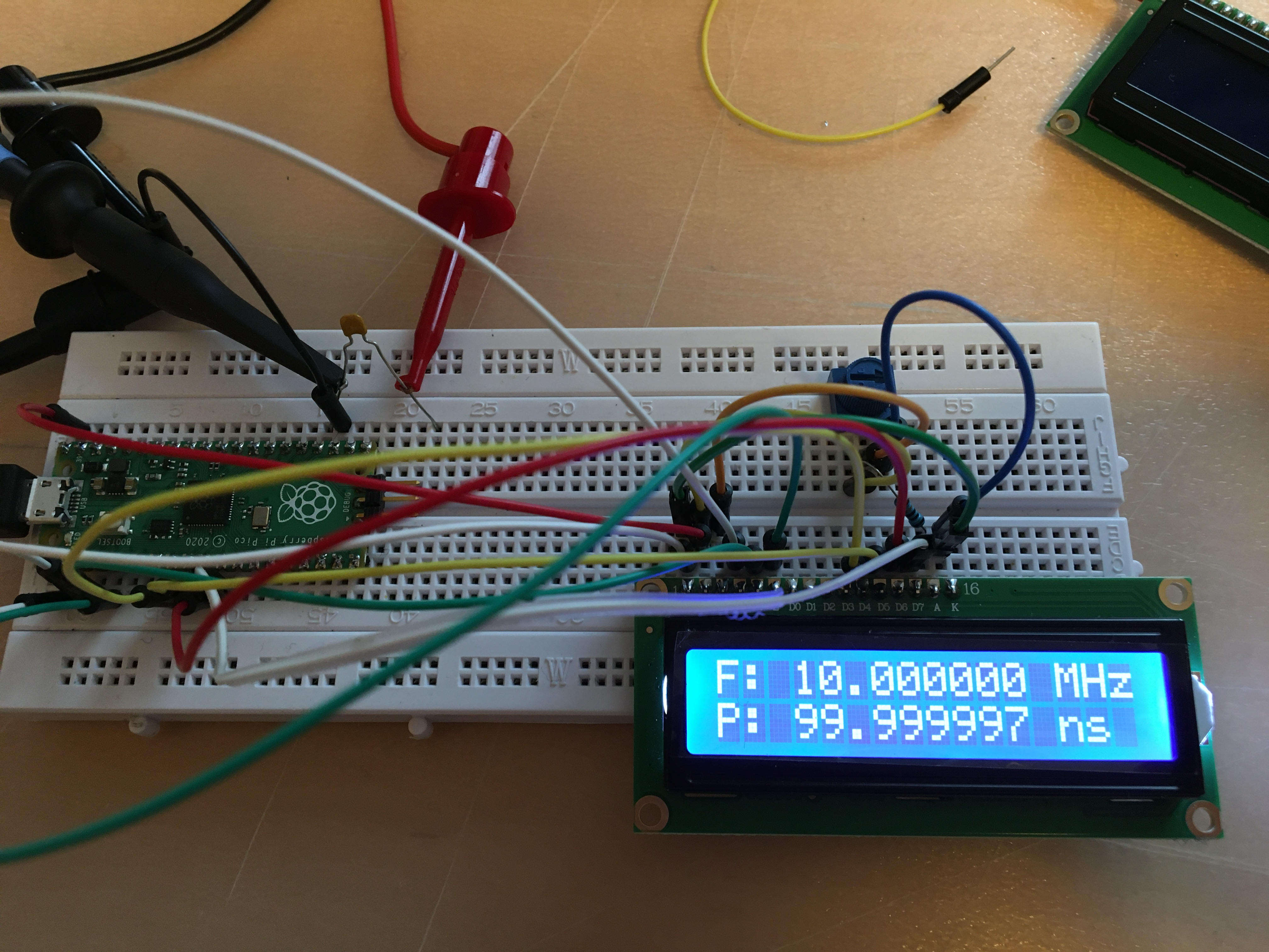
This is with the software as it comes "out of the box" without any configuration and it is gratifying to see this reassuring display.
Next step was to lengthen the Gate time and make it display more digits.

The last two digits are not really useful with this flying leads setup on a breadboard, but it was the needed kick in the proverbial behind to see if I could get it any better, and look for more precision. Down the rabbit hole it went...
The next step was to feed the counter with the GPS 1PPS pulse, because the counter can use it to fine-tune the internal clock to get better precision, and that already resulted in an improved precision. Really nice!
The Pico solution was Michael's way to see how far he could go with the new Pico, but the software was really a port from his STM32 based solutions.
I was impressed enough to now take the next step, and that was to start the hunt for a higher resolution.
STM32 Fmeter-431G
Michael was so kind as to send me a PCB for the FMeter-G431, so I ordered the parts needed to build it. Several were not available anywhere due to the current chip shortage, but eventually I was able to find what I needed, or used what I already had. Unfortunately, I ran into a few snags and ordered some incorrect parts, so had to go through the whole process again. I was able to give Michael some feed-back about his BOM so others will hopefully not fall into the same trap.
One of the traps is that when you use the MAX232 convertor, it inverts the STM outputs and that limits the connection to the PC to only true RS-232 to USB adapters, which use negative logic. I'm typically use a TTL serial to USB convertor (get one that supports 3V3 and 5V levels) but you can't use that with the output signals from the MAX232 because the signals are inverted. In the end, I took the chip off the board and bridged the two inputs pads p to the outputs pads with two 1/8 W 100R resistors to keep the polarity the same. The resistors also "kind of" protect the STM chip.
The Fmeter-G431 project can be found here on Michael's website: Fmeter-G431
Michael also described it on another EEVblog post here: EEVblog
Again I used the IAR WB to re-create Michael's software environment, and this time I was fairly quickly able to build the code myself. I needed to build a new Jlink probe cable interface, and had to order a few parts, but eventually I was up-and-running with this chipset as well. I never used the STM32 family so again I had to learn a lot from scratch. I'm not complaining, it's keeping my grey matter active.
Here is a picture of this setup, again straight after download, no options set yet:

Looks exactly the same as with the Pico. Remember, almost the same software.
Here it still has the MAX232 in place, so I could not change the parameters yet.
Michael intended to have the counter board piggy-back on the LCD display, but I wanted an easier way to test and debug, so I concocted a two socket deal that would allow me to see the display while having access to the counter.
As I already noticed on the Pico version, the counter clock is very critical when you start to increase the number of digits in resolution. This counter has it's own simple VCXO that has pretty good specifications, but when I tested it against my GPSDO, I was amazed how poor it performed, at least lying on my desk the way it is.
In any case, I already knew that the counter has provisions for an external clock, preferably an OCXO, and that was what I wanted to try next.
External Clock
As it so happens, I was already experimenting with two OCXO's that were left-overs from my initial GPSDO project, and I already had plans to build a little PCB with a reference IC to better tune the frequency.
The two OCXO's that I have are a CTI OC5SC25, 5V supply and a square wave output and an ISOTEMP also with a 5V supply and also a square wave output version.
I build the schematic, finished the layouts, produced the Gerber files and uploaded them to JLPCB, my to-go-to board house. Unfortunately, while I was waiting for the boards to arrive, I discovered that uploaded them all right, but did not actually order them. Bummer!

While waiting for the boards, I built a Manhatten style setup on a protoboard, but I had too much difficulty to precisely tune the frequency to that of my GPSDO. Plus it was "flapping in the breeze" which did not help either.
To improve the connections between my GPSDO and the external OCXO, I modified the three frequency input connectors on the counter PCB to SMA adapters.
I used my DSO to monitor both 10MHz signals, and with a 20 seconds high persistance I could easily see the drift from one compared to the other. I'm triggering on the GPSDO and the OCXO is tuned with the trimmer to have a display with no movement. Drifting to the left means it's too slow, and to the right means it's too fast. Simple.
Unfortunately, even though the oscillator is ovenized, temperature plays a huge role on the stability, and the trimmer adjustment is too finicky and simply not good enough.

However, using this setup is already a significant improvement over the local VCXO located on the counter board. I now need to see how much precision I can wring out of this system, also by using the 1PPS input to tune the clock. Unfortunately, to go to 10 digits of resolution, even this is not good enough, unless you calibrate the clock against the GPSDO every time before you make a measurement.
In the meantime, my OCXO boards arrived and I played around with it a bit. I'm not dissapointed actually!
First of all, as I knew and already alluded to, it is very difficult to tune the OCXO frequency with that of the GPSDO. The full trimmer adjustment is only +/- 1mHz, but even a fraction of a trimmer turn will change the frequency a lot.
This plus temperature changes, or rather the sensitivity for it, like drafts or even waving your hand makes it very difficult to exactly tune.
To better use the OCXO board as the external clock input for the counter, I put it in a little plastic container so the temperature inside the box will be a lot more constant after everything has properly warmed-up by the oven of the OCXO.
This is the black box (no pun intended) on the right of the picture.

At the same time, I'm using the trend measurement feature of my 6-1/2 digit DMM to track the adjustment voltage for the OCXO. Obviously, if that drifts or is noisy, so will the output frequency of the OCXO.
When I had the board outside the container, the voltage would move a lot.
However, in the box, after a sufficient warm-up, it appears to be rock-stable!

Note the voltage scale on the left.
I'm also using my DSO to track the alignment of the OCXO output with the GPSDO output to keep an eye on the drift. I can see it drifting a little bit with the 20 seconds persistent setting, but I can't tune it anymore, now that it is in the box.
From now on, I'm using the 1PPS compensation that the counter provides, so that will help with the drift of the OCXO relative to the GPSDO.
The counter display is now very stable at 10.000,000,000,X MHz but has the last 1-3 digits flipping after each 10s gate time, which I think is also a function of the 1PPS adjustment the counter uses.


On the DSO, I can see the OCXO frequency drift slowly to the left, so it's a little slow, but the 1PPS compensation does a good job adjusting the internal clock to be able to show this kind of resolution and precision.
Here is a trace of the report the counter puts out on the serial interface. I capture it with a time stamp to show the gate time.

I think that this is already quite remarkable, with a display of 10 digits, we're already looking at a 100uHz resolution! I'm impressed. Well done Michael!
Looking at a larger sample of the above report and looking at the deviations from the GPSDO 10MHz, there are quite a number of values that are outside of what I was hoping to see:

It means that with the current setup and a steady 100uHz resolution it is still too much to ask for, but it is already better than a 10mHz resolution. Pretty good already, but not good enough.
Initially, I used my Lab Power Supply to power the counter with one channel, and the OCXO with the second channel. While running a trendplot for the frequency-adjust voltage, the second channel of my Siglent SDM3065X switched off, stopping the measurement after about 2 hours. This spontanously switched off happened before, after about a day, but never when I was present. This time I was there. It switches off, just like it would be when the front panel switch is used. Bummer, that's a serious fault but not an easy one to track down. That will have to wait until later. It's now early 2026 and after a few tries, I hav still not found the error.
As a second step, I used a 5.1VDC Wallwart, but the voltage dropped too much to my liking during the oven startup. During the warm-up, the OCXO draws about 600-800mA for about 2 minutes, and this is on top of what the counter needs. I tried a trend plot for the f-adjust again, but was not impressed. I did not want to further occupy my Lab Supply so I concocted a small power supply that is going to be fed by a transformer based 15VDC wallwart. This is one I use for special occasions, because it is not a typical switching supply, hence a lot cleaner.
I'm using an LM317 based voltage regulator to create a 5.1V supply, because these regulators are more quiet than a standard LM7805 type regulator.
At this moment, I'm feeding both the counter and the OCXO supply from this supply now.
Here is the schematic.

The LM317 type regulators have a pretty large tolerance for the calculated voltage setting, but I did not want to add a trimmer because of the poor tempco. I tried the calculated 680R, and that resulted in a desired 5.1V. Be prepared to tweak the R1 and R2 output setting values to get the desired output voltage.
I'll add a picture of the protoboard later. I actually had to progressively use larger heatsinks for the 317, because it got too hot. It has to dissipate about 10V at up to 800mA for a short period when the oven heats up, but even during the stable period, it got too hot to my liking.
I'm now running another trendplot to see how stable the f-adjust for the OCXO really is. I'm also looking at my DSO to see the drift. It is surprisingly stable and it reaches that situation within about a minute or two after power-up. Not bad.
Here is the tendplot of the frequency adjust voltage over a longer period:

Note that the voltage reference chip still needs to "burn-in". It only has had power for several days in total, not even continously. You can see the startup effect that looks huge, but consider the voltage level. We're talking about a swing of less than 200uV. You can also see the temperature effect of the heating in my office being turned low during the night. When I took the snap-shot, it was 9 in the morning, and the heater came on at 8. It turned off at 17:00 the previous day. So a warmer temperature results in a very slightly higher voltage. The GPSDO controlling loop must be able to handle this with ease.
Other than that, it is stable enough for controlling the OCXO.
Improved power supply
I have now added another section to the power supply, because I want to separate the power for the three boards to minimize cross-influences. Experience with my first GPSDO has learned that there are benefits to seperate all the supplies to minimize adverse effects.


The part of the schematic that I did not implement in hardware on the protoboard at the moment yet is for the GPSDO. That will get 8V so the Arduino Nano regulator on the board itself is used to create the 5V, adding one more layer of separation. That LM317 does not need a heatsink.
Realize that this drifting and the difference with the GPSDO is only really an issue when you try to measure something as stable as a GPSDO. For most other applications, this is an already excellent counter! As a general purpose counter, it really only needs a front-end to accept different signal shapes and voltages, but Michael has a solution for such a front-end shown on his site as well.
But, I believe that there is still some more room for improvement and I want to see if I can get more precision and resolution! Further down into the rabbit hole...
Using a GPS 1PPS to adjust the external OCXO
Michael implemented a method in software to tune the internal clock of his counter with a GPS generated 1PPS signal. As far as I understand it, the software only nudges the internal clock (derived from the external OCXO) when it has detected a small difference. Also realize that the 1PPS signal can have a jitter somewhere between 20 to 40nS depending on the GPS module, the antenna, your place on the globe and of course the constellation that is available to you. That's a seperate chapter all by itself.
To test the stability of the hardware as it is, I connected the same 10MHz from my GPSDO to the input of the counter, and also used the same 10MHz as the external OCXO input. The two signals are then in sync, so the display should only show residual noise and other self induced artifacts. The result was very good I thought. I will do it again when I have more of the building blocks ready.
Using a GPSDO as the external clock
To see if I could further improve the current setup, I think that the best possible solution is of course, to try a true GPS disciplined external OCXO for the counter.
Yes, this means I'm going to be using a GPSDO clocked counter to measure a GPSDO. Sounds funny, but that's what I'm going to try to do. Down the rabbit hole some more...
Using a GPSDO as the external clock for the counter
This section is initially a major departure from the counter project, but we'll come back to that.
There are many ways to create a GPSDO circuit, and I can easily use the one I already have to start with or I can try a very different approach, of which I've found a few that are worth trying as well.
To reduce the amount of variables, I'm going to try a mini version of the Lars Walenius GPSDO for this counter first. I know it well enough by now to get up to speed quickly. Over the years since I've had my first GPSDO, I kept scanning for improvements and developments every now and then and I wanted to try them at the same time.
Here is the link to my (long) posting for that first project: GPSDO
While going through this counter adventure, I wanted to try out a few interesting possible improvements. These improvements may not make it in the really minimalistic-version of the Lars GPSDO that I want to build for the counter.
One of the interesting improvements I came across is a design that caught my interest. In my GPSDO, Lars designed the OCXO frequency adjustment by using a 16-bit DAC constructed out of two 8-bit PWM channels, one hi byte, one lo byte. In my own version of his design, I used an improvement that a user recommended for this circuit. The idea is to use a couple of 74HC14 Schmitt Trigger gates that are powered by a stable reference voltage, with the goal to seperate the noisy Arduino environment from the DAC output and create a very clean and stable DC voltage to tune (disipline) the OCXO.
This newer find also used the same 74HC14's but in a very special way. I wanted to try and test this circuit for a possible later implementation into a new GPSDO circuit, so I build it on a breadboard, and used it to tune the OCXO for the counter.
Here is the website where I found the information: dual-pwm-circuit
Initially, to test the new DAC circuit, and drive the 16-bit "DAC" on the breadboard, I used an Arduino Nano and stripped most of the original code from the GPSDO out and only used the bare minimum to allow me to set the 16-bit counter value by hand and send it to the new DAC circuit. This worked very well, but is too sensitive for stable use while still in the breadboard version and without a voltage reference, but this new circuit has a lot of promise.
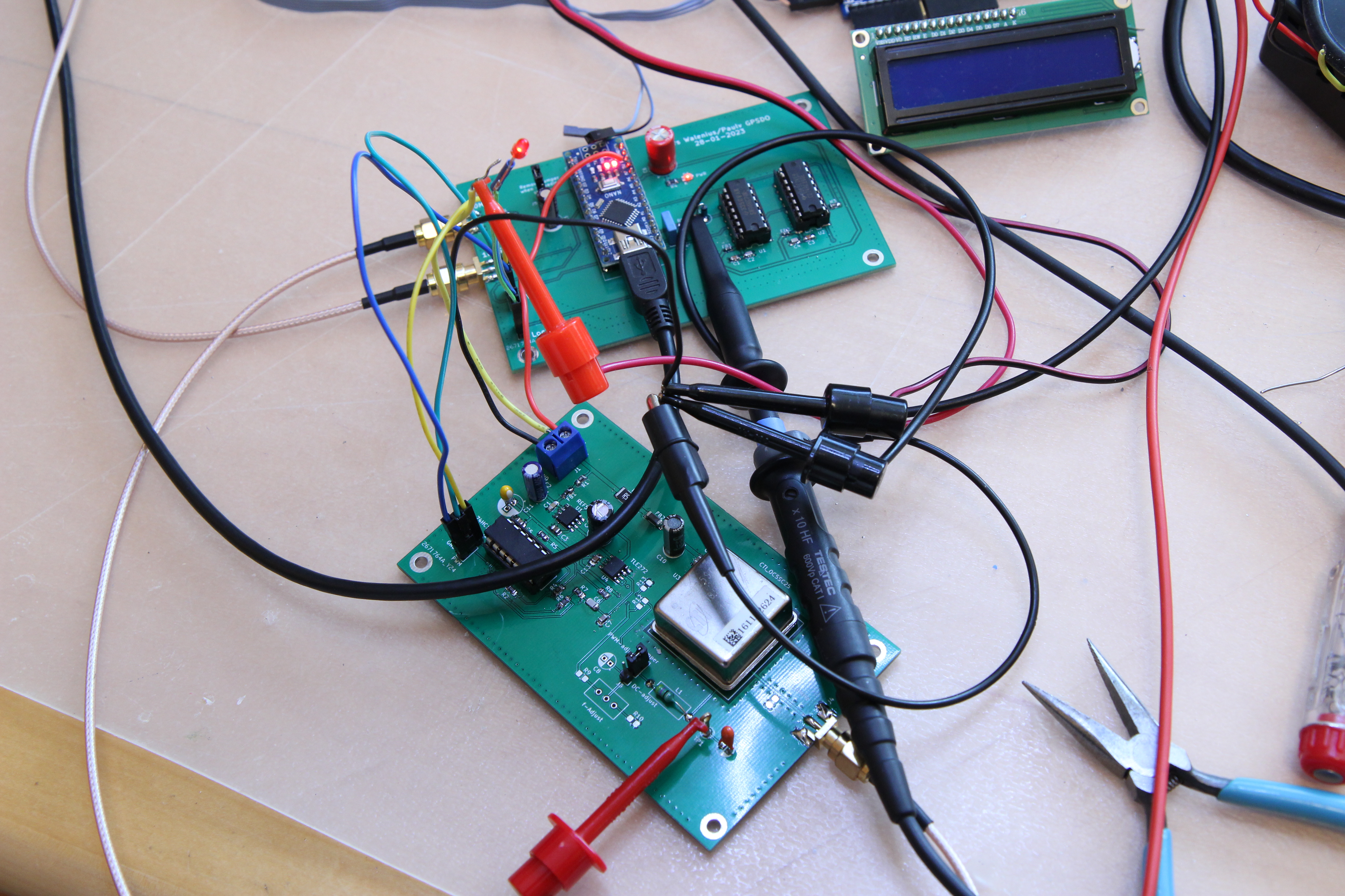
Here is the test setup I was working with to try it all out:

From top to bottom, you see the Fmeter-G431 counter board with the LCD. On the top side of the board is the interface to the Segger J-link. It goes to a little adapter board that connects to the big ribbon cable that goes to the probe. On the left of the board is the connector that supplies power, coming from my Lab supply. It also has the Rx/Tx signals that go to a Serial TTL to USB convertor (3.3V!) that goes to my Laptop. I took the MAX232 out as I mentioned earlier. I use PuTTY to look at the reports and program the options for the counter.
I modified the counter board with SMA connectors so I could feed it with clean signals from my GPSDO to supply the 1PPS and also the external OCXO. To the left of the counter is the 1PPS input coming from my GPSDO. Top right on the board is the OCXO input, and below it the 10MHz from my GPSDO, which is what we measure. Below it is the LCD display, this time showing 11 decimal digits when it shows 9.999 MHz etc. and 10 digits when it shows 10.0000 etc. MHz.
The breadboard below it has the Arduino Nano and more to the right is the new 74HC14 based dual-PWM DAC construction. At the high-impedance output is an Opamp buffer circuit and that goes to the f-adjust pin of the dead-bug CTI OCXO. The blue trimmer you see on top of the OCXO is not used at the moment.
When I took the picture, the OCXO was not exactly tuned to that of the GPSDO, which is why you see a few milliHerz of difference on the LCD.
The new "DAC" circuit on my breadboard is not powered from a reference quality voltage, but is fed by the same 5V supply that powers the Nano and the OCXO. The 5V is pretty clean because it's coming from a second channel of my Lab supply, but it is not the same.
While testing the DAC setting with the new circuit, I was amazed how easy it was to precisely tune the OCXO to the GPSDO. The granularity of the DAC is in steps of 60 microVolts (4V/65535) and it is so much easier to adjust than by using the mechanical trimmer. Even with a 20 turn trimmer range of +/- 1mHz it is way too sensitive. Merely touching it already has an effect. I even could make that adjustment better, but I'm not going to use it anyway, it's only there for testing.
GPSDO Controller
The missing part is the controller board for the OCXO.
I already decided to use the GPSDO I already know pretty well, the Lars Walenius version, with some of my modifications. The original project is described on my Blog. This particular circuit only has the essentials, but I also wanted to try another new feature.
Instead of the 74HC4046 that Lars used to create the pulse that is representing the difference in the two phases of the 1PPS and the 10MHz (Actually a divided down 1MHz), I am now using a dual 74HC74 flip-flop, that supposedly does the same thing. In the schematic, this is U1A and U1B.
This idea comes from a country fellow, Erik Kaashoek. More information on his github
When the PCB came in, I tried the 7474 idea from Erik, and I tried it with all the 7474 technologies I had. The 7474, the 74F74, the 74LS74, the 74AHC74, and the 74HC74 also from a few different manufactures and they all worked flawlessly. So I decided to use the 74HC74.
The only notable omissions from the Lars' design for the counter version are the two temperature sensors, I don't plan to use them, and if I do need one or the other, they are easily added.
Note that when you want to use this schematic, you have to apply the modification that I made to Lars' sketch, that uses the D10 port to drop the voltage from the C7 capacitor, after reading it with ADC0, through R7 to GND. Lars used a 10M resistor to GND to bleed the voltage, but I wanted to eliminate the 10M value due to its inherent Johnson noise and make sure the ADC measures at the real top of the voltage, not already loaded by the 10M. As a quick and easy elimination, you can replace R7 with a 10M, and set port D10 to a low during start-up, or solder it to GND.
UPDATE & WARNING:
After a lot of testing I found that the 7474 circuit is NOT working the same as a 4046. While experimenting with another method to do a phase difference measurement, I prototyped both the 4046 and the 7474 circuit on a breadboard, and fed them with my main GPSDO 10Mhz and the 1PPS signals. Now granted, the 10MHz is not used in the GPSDO, only a 1MHz signal, but still.

Above is a normal situation. CH2 (blue) is the output from a regular 74AC4046. CH1 (yellow) is the output from the SN74AHC74 circuit. The signal from the 4046 is lagging 10ns behind that of the 4046 (must be a propagation delay), but that is not an issue. The point is that the pulse durations, which reflect the phase difference should be the same, and they basically are.
While making some measurements I saw that there are sometimes weird results. Have a look here:

Most of the time, the two circuits are in agreement, but every once in a while (several times per minute), there is one, sometimes up to several pulses where we have an incorrect measurement. Someone on the EEVblog, where I reported this behavior, commented that this is probably due to the 10MHz=50ns pulse width. If it's a tad more, the pulse shifts, and causes the glitch. Erik, the original designer I asked reported that he has no clue why this is so.
Due to the saw-tooth behavior of the 1PPS from the NEO, there are actually about 4 to 9 steps (one per second) of drift within the saw-tooth cycle. Both circuits behave the same. However, when the 7474 circuit is off, and produces the glitch of a few ns, it can be from one to several succesive cycles within the saw-tooth cycle and then it resets and is the same as the 4046 again.
I tried all technologies I have, and even from different manufacturers, like the SN74HC74, the 74LS74 and even a 74F74, and lastly even a "normal and old" SN7474NV. All have this bad behavior at 10MHz signals.
Here is the SN74F74 also showing the problem.

This F (F means fast) technology is still much slower than the modern AHC and HC technologies and shows a glitch with a lower amplitude, which is why I missed it earlier when my trigger level was set higher-up.
The conclusion is that the 74ACH74 circuit seems to work fine with 1MHz inputs, and others have not reported any issues with those speeds, so it's safe to use this circuit as a replavement. However, keep in mind that the 4046 has special, mostly undocumented circuitry for the input signals, that the 7474 does not have.


The controller PCB has arrived and I populated it and verified the various signals. I then loaded the Arduino sketch and hooked up the PWM connections from the controller to the breadboard circuit I build earlier.

After verifying that everything functioned, I calculated the gain (28) and saved that and the TC setting (4) to the EEPROM and started to Run. It didn't take long, only a few minutes, to get a Lock because the OCXO was already warmed-up and a TC of 4 is the lowest setting. The Lock is also shown by the red LED floating on the left side of the PCB. Success!
Now I need to build-up the OCXO PCB version that you see in the lower right foreground and add that.
Using the OCXO and new DAC controller
Here is my design using the new dual-8-bit PWM DAC circuit:


The output of the dual-PWM DAC, is taken from C7 but that point has a very high impedance. So high in fact that when I clip my 10 GOhm input impedance DMM leads to the output, the voltage drops. This is why I use an Opamp to buffer the DAC output and drive the OCXO. The two resistors on the output, R12 and R13 are there so I can reduce the full 4V swing of the DAC to a much smaller voltage change for the OCXO. I decided to call this "compression" in my posts. This compression increases the sensitivity and gain for the PID loop and is what I already do on my "real" GPSDO. It reduces the V/bit resolution of the DAC. R9 and R10 need to be tuned for the OCXO you're going to use. They need to set the center of the trimmer to the sweet spot (exactly 10MHz) of the OCXO, and that voltage is different for every one of them, even from the same type. After tuning the circuit when the OCXO is stable after a burn-in, you can replace the trimmer circuit with low tempco resistors for R12 and R13, and only use the jumper on positions 3 and 2. At a minimum a tempco of 50, better is 20 or even lower, unless you can keep the temperature of the whole setup very stable. (we'll get to that)
Due to an omission from my part, I did not include SMD pads for R15 on the PCB. This resistor can be added in the circuit by soldering it between pin 3 and 2 of the J3 jumper connections, and bridge 2 and 1 together. Start out without this resistor though.
The jumper is there so I can easily switch from a trimmer adjustment and back to the Arduino controlled DAC or all three positions during the burn-in and tuning phase. This is basically the same design I show for the other OCXO adjustment a little above.
Here is a picture of the controller and the OCXO/DAC board together.
Note that as a first power-up, I did not populate the trimmer section on the OCXO board.
Nest step is to connect it all to the counter and start to use the new circuit as the external clock.
I hooked it all up and tried from a cold start. It took 91 seconds for a lock with a TC of 4. The reciprocal counter no longer needs the 1PPS signal so it's now running from the GPSDO generated clock. To remind you, the 1PPS that I use for the counter GPSDO is the same as is used for the "big" GPSDO that I'm measuring the 10MHz output from. This is using a NEO 8MT, which should have better stationary stability for Timing measurements. (we'll get to that later as well)
Now I need to track the reciprocal counter output for a longer period.
First of all, I noticed that the counter was reading about 160ppb too high. When I wanted to compensate for that in the counter software, I saw that there was already a factor of 160 in. Duh! That value was stored in the EEPROM - don't ask me how and why. After some experimenting I found that with zero compensation, the counter was about 10ppb too high, so I entered a -10ppb compensation.
That was still observed with a TC of 4, meaning that the OCXO is adjusted with an unfiltered (rapid) GNSS correction. The correction is jittering due to the up to 20nS (sawtooth) jitter of the 1PPS. In effect, this is the short-term GPS performance. To get the best out of the OCXO, we need to filter (dampen) the 1PPS jitter with a much longer time factor.
Below is the counter output at a GPSDO TC of 256. This is a kind of middle of the road value, that is OK to use when there are no other GPSDO software compensations active, and the OCXO itself is "flapping in the breeze".

The counter is now reading the 10MHz of the "real" GPSDO with a resolution of +20/-10ppb or 9 stable decimal digits.
The following two graphs show the correction (discipline) of the OCXO frequency when the difference between that and the 1PPS is deemed too large by the software.
Here is the deviation in a nsec graph:
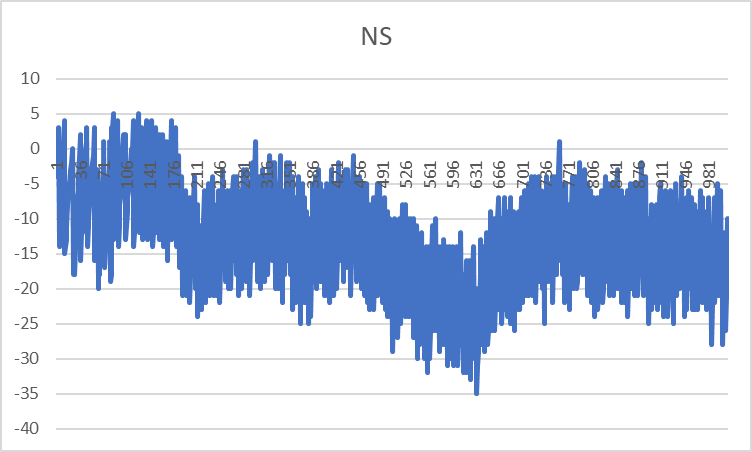
It's easy to see the jitter and the longer term drift.
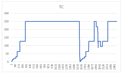
And here is the compensation for the OCXO:

The DAC value was dropped by one count to bring the difference back in check. Look at the NS display to see the upward correction in effect.
Important is the granularity of this adjustment, which is called Gain in the Lars' software. Right now, the DAC output ranges from a few mV to the full 4V reference, which means that we have 4V/16-bit = 60 microVolt resolution per DAC step. That's still way too high, and will result in slamming the OCXO in shape, rather than gently nudging it, so we need to lower that.
To increase the resolution, you can loosely fix the f-adjustment pin of the OCXO to the sweet spot by using clamping resistors, and then let the DAC control the sweetspot. The "fighting" of the DAC output against the sweetspot clamping will in effect reduce the actual voltage swing of the DAC output, in return increasing the resolution, and that means a higher Gain for the controlling loop of the sketch. Hence my compression term. A resistor put in serial between the DAC and the clamp will further lower the DAC influence, in turn increasing the resolution and therefore gain.
Here is a screenshot of the DSO that is measuring both GPSDO 10MHz clocks. Blue is the "real" GPSDO, and is used to trigger the DSO. Yellow shows the counter GPSDO. There is some drift of about 40nS (shown by the light yellow area), which is the result of the different TC values of both GPSDO's and of course the temperature and other effects.

Next step is to try to see if I can improve on that differential drift.
The power supply board finally came in an I populated and tested it. Works fine with one, already known caveat, the LM317 that feeds the OCXO will get pretty warm during the initial warmup of the oven. After that period it's fine. To keep the heat down, I use a 12VDC input and do not go beyond 15VDC. This board can be used inside a metal enclosure, in which case the LM317's can be mounted (isolated) on the enclosure itself, eliminating the heatsinks for the standalone version as I have it here.

The outputs are on the bottom. From left to right, +5.1V for the counter, +5.1V for the OCXO and +8V for the Arduino Nano.
I actually made a small mistake on the layout. The mounting holes for the heatsinks are grounded, which means that I have to insulate the LM317's from the heatsink. Something I overlooked. When I publish the Gerber files, I'll fix that.
Initial setup for the OCXO/DAC
After the first functional tests, it is time to get down to business and start to work on the DAC resolution. To start with the DAC/OCXO circuit, do not populate R12 and R13, and start without R15. Put a jumper on the 1 and 2 positions of J3 and now select the proper resistor values for R9 and R10 to make sure you can set the OCXO output very close to 10MHz with the trimmer about in the middle. You can now use this setting to burn-in the OCXO. When that is stable enough, you can now add the GPSDO controller and connect the DAC by putting a jumper on pin 3 and 2 of J3.
When that works to your satisfaction, you can now start to reduce the DAC swing from 0..4V to a lower range around the sweet-spot by adding R15. R15 is used to reduce the Volt/bit range of the DAC and increase the gain for the PID loop. The goal for the counter version is to get the gain in the 300-400 range. (Lars recommends 500 for the GPSDO but that's too high for this current counter version. I tried it.) I actually first used a trimmer instead of R15 to try it out and when I was satisfied, I switched to using a resistor. Don't select a gain that is too high, it will hamper the startup period. I ended up using a 82K value for R15 and that resulted in a gain of 387.
With this setting you can now fully tune the software and do the first runs to determine the gain and try to get a lock. Make sure that before you do that, the system has warmed-up sufficiently.
With that done, you can now linearize the DAC range. Go to my main GPSDO blog here to see how that is done. Search for "Setting the ADC linearization parameters". In my case that resulted in a Min of 985 and a Max of 227.
And now you're ready for more testing and tuning.
After a serious amount of burn-in, and when you're happy with the setup, you can now populate R12 and R13 with low tempco resistors. To calculate the values, use the R9, RV1 and R10 values. You can now use R15 on position 3 and 2, and remove the connection to pin 1 to keep the high tempco trimmer section out of circuit. After you placed the R12 and R13 resistors, you need to go through the gain setting and linearize the DAC once more to tune it to the new parts.
Testing the Counter Version of the GPSDO
For the last several days, I have been playing with the settings of the GPSDO to make it more of a reciprocal counter version, rather than a long term frequency standard.
To that extend, I have also modified the sketch to make the GPSDO get a lock faster and maintain a stable frequency output after the warm-up period for the oven. The idea is that when you want to use the counter for general purpose measurements, you power it on, and want to make a measurement fairly quickly, and do not want to wait for several hours to get a traditional GPS lock.
To make the sketch a better fit for the counter application, I also wrote a function that would automatically increase the time constant (TC) while keeping a lock. When the difference between the 1PPS is drifting too far away, the TC is automatically reduced to keep the lock. If the lock is lost all together, the TC is reduced more dramatically and the process starts again. To get a lock quickly, I start with a TC of 4, which is the unfiltered setting and progressively increase the TC while trying to keep the lock. In the originl code, Lars used a lock formula that would only give a lock indication when the difference with the 1PPS is less than +/- 100 ns for a period of 5 x the TC. This number of 5 is the lockPPSfactor. I changed that to a value of 2 because we're less interested in a very long term result.
Here is a run while using the new automatic TC setting where I disturbed the system about half-way:
As you can see, the TC is rapidly and progressively increasing from 4 to the maximum I set at 250. (the horizontal scale is in seconds) I then disturbed the system. It looks dramatic but it actually never lost the lock but started the process to first rapidly lower the TC and then to increase the TC again. It then was about to loose the lock at 250 again, so it once more lowered the TC in steps, and then recovered back to the maximum at 250. I did this for TC settings between 100 and 800. It takes a lot of time testing it out...
After running many tests over several days, I also decided to dynamically change the lockPPSfactor. I now start with 3 and progessively reduce it to 1 with higher TC values and go down when the ns is drifting out of control or when the lock has been lost.
During the testing, I tried several TC setting that would give me the fastest lock results, and the most optimum filtering/damping, which is depending on the TC value. A low TC adjusts the OCXO rapidly, but it will show signs of the 1PPS drift and saw-tooth effects. A larger TC will increase the filtering and dampens the swings, but then the PID loop will be more sluggish to react.
Right now I'm using a TC of 250. With that, the DSO shows a drift between both GPSDO's of about 20-30ns over quite a long period and I have counter readings of the main GPSDO with stable 10+ digits.


The sketch will be posted on my Github when I'm done.
Finding the optimum TC
After I replaced the 7474 solution with the original 4046, I ran a test to find the optimum TC for the OCXO.
Here is that result in a Timelab plot (the black lines in the graph are mine):

I added the two black lines to show the optimum point at the intersection of the two. This shows that the OCXO can be used with a TC of about 300 maximum. After trying a few higher TC's, my wet-finger hunch to select a TC of 250 was right.
A dedicated mini-GPSDO for the Counter
The next step was to design a dedicated minimum GPSDO board that will be specifically designed for this reciprocal counter use. It is also time to put everything in an enclosure to reduce the temperature/draft effects.
Here is the more simplyfied GPSDO schematic diagram that I ended-up with:

This is really a minimum GPSDO circuit based on the Lars Walenius design with some of my own and other contributor enhancements. This is also a simplified combination of the other two boards that I used to experiment with obove. The idea is that this design can be used as the external clock for any counter. All it needs is a 1PPS input from a GPS system. I have used THT components just because I have them in stock. If a smaller size board is required, you can easily change the components to all SMD.
The board needs two power inputs, an 8V-100mA for the Arduino Nano, and a 5V-800mA for the OCXO. The 8V supply goes straight to the Nano, and I let it use it's own 5V regulator to supply the Nano board. The 8V is also used with a separate 5V regulator, to supply the other components with power to create some power and noise separation. I decided to eliminate the 4.096V reference chip, for this purpose, it is not really needed. We'll see.
Because I need at least three 74HC14 gates to clean the 1PPS signal and also to elevate the OCXO output to drive the 10MHz signal, I decided to use two more gates and use them to separate the PWM outputs from the Nano. Again to create some more noise separation. This will mean a change to the Nano script because the DAC outputs will now become inverted. I have not posted the script yet, but for this hardware I'm using gpsdo_ctr_V365.ino.
Here are the board layouts (taken from the KiCad 3D viewer):

There is again no copper underneath the OCXO, so the board does not suck the heat away from the OCXO metal can. You can use a number of different OCXO's, because many have the same footprint. Check it out before you solder them in place though! I made the pin-holes a little larger so it's easier to fit them, and also remove them.
I have used the footprints for SMA adapters for the 1PPS and the 10MHz signals, but you can easily use a braided cable soldered to the pads to connect the board.
Here is the board in action:

I tweaked the DAC output range by populating the three resistors to get as close to a 500 gain as possible. At this reduced adjustment range, it is more difficult to get the sweet spot set by a DAC value of 32767 (the mid range) and also the linerarization values that will be accepted by the script.
This circuit works well, and can be used as a general purpose GPSDO or as an external clock for a (reciprocal) counter that needs high stability and precision.
Micro-GPSDO
I recently found an interesting approach that I'm investigating now. It uses a more modern version of the 74HC4046, unfortunately, apperantly the best one they use in this design, a Nexperia 74HCT7046 is discontinued and hard to get and the even more advanced 74HCT9046 is obsolete and I cannot find any stock at my prefered suppliers. I wanted to try one, but that no longer makes sense. You can still get them from a few sources, but make sure you can trust them. I ordered two of the 74HC7046, we'll see if they are genuine.
I bread-boarded the circuit that I found here:
http://www.knietzsch.com/amateur_radio/ham_index_s-GPSDO.htmhttps://www.dl4zao.de/projekte/index.html#a1968
I tried a couple of things and I'm rather impressed with how this works, especially on a bread-board.

Here is what you see: The left circuit on the bread-board is a 74HC4046, to the right of it, the equivalent circuit based on a 74AHC74, and the two chips to the right are two 74AHC390 decade counters. I'm only using one of the counters at the moment to reduce the 10MHz to 100KHz. Just above the bread-board is the Isotemp OCXO up-side down.
Micro-GPSDO
And here is the schematic of this very simple circuit:

Let me explain. The idea is that you use a NEO GPS receiver and program it to output a 1KHz, 10KHz or 100KHz signal, instead of the 1PPS. The 1PPS has the well known phase jitter of about 20ns sometimes up to 30ns, as a result of the GNSS reception signals. On top of that, this phase jittering is also undergoing a "saw-tooth" effect based on the GNSS. The better the view of the sky for the antenna and the number of sattelites and constellations in view are, the less this jitter will be but it will always be there due to reception and atmospheric conditions.
You can program the NEO to output other frequencies than the 1PPS and the most obvious one would be 10MHz. However, because of the internal 48MHz OCXO clock on the NEO board, you should only use frequencies that are divisible by 48. 10Mhz results in a divisor factor of 4.8. With fractional numbers, the internal hardware skips clock cycles to stay in sync. Think of a leap-year correction. This skipping cycles is a major problem. So only when you divide by a factor that is divisible by 48 to get round numbers, you get clean signals. The 1, 10 and 100KHz can used for that reason. Note that these output signals still have the up to 30ns jitter, but they don't have the "leap-year" jumps.
Testing it without a NEO
While I was waiting for an additional GPS antenna, I wanted to test the circuit out without a NEO. I used my frequency generator that is fed by my GPSDO, and I have set it to a 1, 10 or 100KHz output.
I tried both the 1KHz and the 100KHz option and settled on the 100KHz because I did not see a lot of change. Using 100KHz saves one 390 decade counter chip.
The Isotemp OCXO 10 Mhz output is divided down to 100KHz by a 390 counter, and both signals are fed into the 4046 to do the phase comparison. The result is taken from the PC1 output from the 4046, and that produces the well known phase difference that is used in all the GPSDO circuits I have worked with. This pulse is then filtered to get a DC voltage that goes to the frequency adjust pin of the OCXO. The DC voltage goes up and down with the phase pulse and will eventually setttle when both signals are equal in phase, hence a lock condition.
Below is the resulting phase drift of my GPSDO 10MHz and the Isotech OCXO in the above circuit settling over about an hour:

If you look up a bit in the blog, you see that the "real" GPSDO has about 20ns drift, this one about 30-35ns. Still very respectable.
NOTE
My DSO was a little confused and does not display a correct frequency in the upper right corner, but rest assured, it is a precision 10MHz down to the microHz. I saw more frequency errors so I ended-up rebooting the DSO and that fixed it. Go figure. It uses a Linux OS, not Windows (;-))
After the initial testing, I build a bit more permanent circuit on protoboard to see if I can get even better results.

BTW, the designers used the 7046 or the 9046 variants because they use the "lock" pin these variants have. However, this is not a very good indicator for a lock, so they use software to make it a more reliable indicator. They also use the Arduino Nano to setup the NEO, and read the NMEA messages.
I also experimented with using the PC2 output of the 4046, but the system kept hunting and did not settle soon enough. The PC1 output settles much faster.
Unfortunately, the protoboard version did not bring the improvements I was hoping for. After a cold-start, the system is very quickly getting close to a lock, but then hunts around the phase lock point a while.

Here you can see the relatively fast ramping up to the phase lock point, but then it starts to hunt. Every once in a while, there is a large glitch on the frequency control voltage (see below), the lock is lost and the process starts again. This may be due to the fact that this OCXO has not been used a lot, since I used the CTI in the other tests. It also may be something else...

The Bliley OCXO I'm using in my main GPSDO has a tendency to create glitches on the output as well. It is extremely stable, by far the best of all the OCXO's I've tried and used, but still there are jumps in the DAC value, the result of a frequency output glitch in the OCXO.
I'm unsure at the moment which is which, so I need to spend a little bit more time watching this circuit behave.
The good news is that the controlling loop is pretty quickly responding and eventually, everything is stable again. As with the other circuit, this circuit is also flopping in the breeze, and seems to be sensitive to room temperature changes, as all the other circuits I tried. No change there..

The regulating voltage swings are in the microvolts so could benefit from some power supply enhancements, and it needs to be in an enclosure of sorts. I think it could also benefit from a seperate power supply for the controlling chips, apart from the OCXO like I have on the other GPSDO. I think I'm going to try that even though it will mean a few additions to the circuit.
Testing it with a NEO
The two NEO versions I have, a M8N and a 6M do not work with the supplied antennas in my environment. When the NEO's are on my desk, I don't have a good enough reception to have them see any satellites.
I had to order an additional external "puck" antenna, so I could try my NEO M8N. Unfortunately, I found out that I cannot update the firmware on this fake NEO so it cannot support the Galileo constellation. More importantly, I also discovered that although I can change the 1PPS output setting in u-center, the output does not change.
I have another NEO 6M based board, but that does not have a micro-USB, nor an SMA antenna adapter. I had to modify the board by soldering a small shielded cable with an SMA adapter to the antenna connection on the board so I could connect my antenna. And that works. I can also program the NEO to a timing pulse of 100KHz, 10KHz, or 1KHz.
The other good news is that when I save the configuration to the on-board i2c-EEPROM, (a 24C32) it actually stores the settings. Powering the NEO off, and turning it back on works. It started up with the configuration I set it to, and the 100KHz pulse was there. That is very good news, because I will not need an Arduino Nano to set it up after it is powered on like the original designers do. I wonder why they didn't use this feature? Well, they also wanted access to the NMEA messages, but there is no need to set it up at every power-on as they do.
So how does this contraption finally work in the "real" configuration:

First of all, the GPS unit had been on for a while, so it already had a stable sattelite lock.
However, as you can see, the mini-GPSDO only needed a few minutes after power-up to get a pretty stable lock, although with a tiny bit of hunting around. Mind you, this was still during the warm-up period of the OCXO! The DMM display did not start at the very beginning, because that would have ruined the resolution on the display. I waited until is was in the ball park before I started to record.
On my DSO, where I look at the big-GPSDO and also the output of the mini-GPSDO, I can visually see the waveform drift a little, somewhere around 20ns for several minutes. Sometimes there is a glitch.

After the glitches, it quickly gets back to a stable display as you can see. The controlling voltage level changes around the sweet-spot to adjust the OCXO are very small, and also depend on the supply voltage. Right now I'm tapping the 5V for the two IC's directly from the OCXO where I connect to my lab PS. I will change that and use my dedicated power supply that has two different regulators for the OCXO and the GPSDO.
I'm now using my special GPSDO/Counter supply so we have better seperation between the OCXO and the GPSDO logic. The NEO is still powered through a USB serial convertor that provides the 3V3 supply for the NEO. This is also not the most stable supply. To see how far I can take this further, I ordered a new NEO-6M board that has an SMA adapter for the antenna, and it also has an on-board regulator that allows you to supply it with 5V. The resulting signals are still at the 3V3 level, but I think that the 74HC4046 can easily handle that.

The jitter/drift of the OCXO output over a long time is still up to 40ns, compared to my main GPSDO, but the source of the jitter is still unclear to me. The 100KHz signal from the NEO should not have any master clock related adjustment skips, but the adjustment voltage is changing too.
I'm intrigued by this simpel solution, so I also started to design a PCB. Here is the circuit diagram I'm going to use.

Before I continue, I want to play with the 74HC4046 some more and see if I can concoct the equivalent of the lock detector circuit that is on the 74HC7046 chip. If that works, I'll continue with this circuit, otherwise I'm going to try to switch back to the 74HC74 circuit.
When testing this lock indicator circuit, I discovered something else. Because I am using the Isotemp OCXO in the dedicated counter GPSDO, I switched to the CTI for this mini GPSDO. When I powered it up, it would not lock at all, it kept searching (voltage swings from minimum to maximum) without stabilizing. The original designers used a jumper to select between the PC1 output, that I had been using for the IsoTemp, and the PC2. When I switched to using the PC2 output, it locked almost right away, meaning that the hunting for a mid-point is very gradual. This is a little strange when you look at the internal details provided in the 4046 datasheets.
When I looked at the so called Lock Indicator on pin 1, it is apperant why the designers had to use software to make sense of this indicator. For this application, it is pretty much useless because the resulting output signal is almost immidiately stable showing a lock, but the lock indicator cannot show small variations.
I will test it some more when the 74HC7046 arrives, but I don't have very high expectations.
Proof that the 7474 is NOT a replacement for the 4046
The next step was to see if we can use the 74AHC74 circuit for both OCXO's. Well, that answer is a resounding no. The circuit is very unruly around the sweet spot and never settles down. I tried the positive and negative outputs to no avail. The problem with the 7474 is that around the sweetspot, the output of the FF is at exactly the half point of the 100KHz cycle and collapses to either a full high or a full low when is is not quite exact and that causes the frequency adjustment for the OCXO to swing between the rail and GND without ever settling down.
The output of the 4046 stays a 100KHz pulse so the integrator does not get janked as much. My explanation that it works in Lars' GPSDO is because I think it has so much filtering that this effect does not show up. Well, at least I tried, but it also shows the additional circuitry in the 4046 and the so called flip-flop in the datasheet diagram is not really a 7474 like flip-flop. There's a lot more too it, apart from the signal conditioning for the inputs we already know the 4046 has.
Continuing with the 4046
Here's another start-up sequence, looking at the frequency adjustment voltage. It only takes about 3 minutes for the OCXO to get tuned to the GPS signal.

Nice and very promising...

I received the PCB's and build-up one of them.

Because my new NEO did not arrive yet, I had to use the old 6M based one. It has no on-board 5V to 3V3 regulator, so I used my serial interface to provide the 3V3 power for the NEO. I also had to use wires to connect it to the board because the pin-out of this NEO board is different.
When I started to use it, I found that the value of R4 (the series resistor in the 1PPS/100KHz output) was too high, so I changed it to a 10R value. Using the CTI OCXO, I again had to use the PC2 output of the 74HC4046 to get a lock. My 74HC7046's still did not arrive yet.
Here is the complete setup with the Micro-GPSDO providing the external clock for the counter.

And here is a view of my workbench, keeping an eye on the whole system.

The PC looks at the NEO coverage, the DSO compares the main GPSDO 10MHz against the Micro and the DMM measures the adjustment voltage going to the OCXO on the Micro board.
Here is a picture of the setup using a NEO 8M board. This board has the proper pin-out, and even a micro-USB connection. On top of it is the useless antenna for indoor use that comes with the NEO board.

GNSS Performance issues
Further going down the rabbit hole...
While making all these recent measurements and looking with more attention at the NEO performance, I discovered that the location of my two GPS antenna's is the cause for quite a bit of instability. I always wondered why my main GPSDO was less stable than I was anticipating, and I knew I did not have an ideal view of the sky, but since I had plenty of sattelites (10-12) in view with a reasonable strength (above 20dB), I thought I was OK.
While learning a lot more about the two NEO's I'm now using, I was finally able to zoom in on the issue and show the weakness. My two GPS antennas are located outside my home-office window, on the metal window sill, that is East-facing, and there is another appartment level above me further blocking the view. My GPS-antennas only see the Eastern hemisphere, with a chunk of North and South and only straight up.
I happen to live on the corner of the complex, so I tried a NEO with the GPS antenna located on the corner balcony, now getting a full East and a full South view. This improved the stability dramatically, with many more sattelies in view, and a dramatically improved deviation map.

The above map is created by the NEO 6M, with the antenna on the South-facing window sill and only for a few hours. A map over a 24 hour period looks really wild. The "wondering about" with a deviation of 75 meters is a testament to the poor reception. I did not save the same map when I used the NEO with the antenna on the corner of the building, but I remember it was in the 2 meter range, which is a dramatic improvement. I'm sure this "wondering about" is the cause for the contineous drift between the 10MHz signals from the two GPSDO's.
The challenge I'm facing now is how I can place my GPS antennas on the corner location, and get the antenna cables to my office. This is not an easy feat, as I need to go through the very thick concrete and brick outside wall and also an internal wall. Initially, I did not see how I could string the wires on the outside of the building because I can't see a way to fasten them. Hmmm.
Here is onother possible solution, using a GPS repeater:

Here is a picture of the cheapest kit that I found for about 100 Euro's on Aliexpress:

The white dome shaped antenna receives the outdoor GPS signals, the grey box amplifies and transmits them indoor again through the black antenna. You should be able to use the same "puck" antenna's that come with the NEO kits if they are less than 15 meters away. So far, I did not find a lot of information on the EEVblog using this contraption for a GPSDO.
Could that be the answer?
As an in-between, I'm going to place a puck antenna on the corner balcony position and string a 20mtr antenna extention cable temporarily on the outside of the building to my office and see what improvements that will bring. That is the least expensive and least destructive option for the moment.
Unfortunately, the 20 mtr long cable to the balcony corner has a higher loss than I hoped for and drops the sattelite signal strength by about 20dB, making them borderline usefull. I did test it with u-center on my PC located on the balcony and the results are that I get a very good reception East and part of the Northern hemisphere, South and a good part of the Western hemisphere. Most of the sattelites in view are located in the East, but also a few good ones in the West and that should help with the positioning and hopefully with a more stable timing pulse. That at least solidifies the new position for the antenna.
After quite some searching, I found an in-line GPS signal antenna amplifier, so I'm going to try to use that. Judging from the supported frequency, it will not really support the GLONASS GNSS as they communicate with 1.602 MHz. GPS and Galileo use two bands one of which is the 1575.42MHz band, so that will be OK. It will take about 3-4 weeks to get it though. This amplifier gets it's power from the 3V3 or 5V present on the antenna cable like the puck does, so it does not need an external power supply.

When I got it, I had to open the box to see what's inside, because I could not figure out what is input and what is output from the Chinese text. Here are the innards of the amplifier:

The IN and OUT markings are now mine, after looking-up the amplifier chip the is used and following the connections. I can't make sense of the Chinese text and the direction of the arrows does not help either. There are only a few parts in the box, and the "interesting" way of using lots of glue to mount the PCB, is not surprising, really. Glue must be very cheap over there.
The main part is the 1.575 GHz amplifier, a MAALSS0042 from MACOM. It only has one input and one output and uses two ferrites at the input, following the datasheet.
This chip passes the DC component, needed for the active antenna, and that same power is also used by the amplifier itself. Clever!
The results are quite good. Instead of signals in the 20dB range, they are now lifted by the advertised 28dB so I'm getting decent results judging from the u-center software.

As you can see, with the 8M board, I can receive GPS, Galileo and GLONASS GNSS.
With the amplifier installed, and after finding a creative way to string the cable on the outside of the building, I can now cut the 20 mtr antenna extension cable length by a few meters and reduce some cable losses. With that, I can start to monitor the results and see if I can indeed see some noticeable improvements.
I also received the new NEO 6M board, the one I designed the layout for. Unfortunately, what I didn't expect was that the yellow 90 degree connector that is mounted on the board prevents it from sitting flat on the PCB.

Cutting the plastic holder for the 5 pins to seperate them, allowed me to carefully desolder the pins one by one, and again by carefully removing the solder from the holes, allowed me to solder a straight 5-pin connector to it.

I added a plastic 10mm support stud using the mounting hole on the board such that the PCB is not leaning on the connector. I had to use SMA adapters on the antenna cable because the ending SMA connector is the wrong type. That will be solved when I reduce the cable length by a few meters and also reduce some of the cable losses. When I removed about 6 meters from the cable length, I noticed that the signals improved noticeably with about another 5-8dB. It all helps...
In the final enclosure, I can also use an SMA panel connector, and internally use a cable with an IPEX connector to supply the antenna signal to the board.
This particular NEO board with the "fake" 6M (meaning not a genuine ublox chip but a Chinese replica missing some functionality) does not allow me to add/receive the GLONASS and Galileo GNSS, so I'm reverting to only using the GPS GNSS signals. I have about 4-9 sattelites well above 30dB so that should be plenty. In the chart below I indicated my remaining blind sport within the black lines.

With the GNSS antenna now positioned on the South-East corner of the building, I have a 180 degree view of the East and the South, and with 90 degrees North and West, so there is only one quadrant I'm blind to, and that is the North-West quadrant as shown above.
NEO board pin layouts
When you order these Chinese NEO boards, you have to pay attention to the connector layout. I have an 8M board with VCC-GND-TxD-Rxd-PPS connections in that order which is what I could use on my mini-GPSDO board. This board does not have the connector mounted. The 6M board I'm using in the picture above has the same pin layout, but comes with a connector. However, I also have a NEO 8M and a 6M board with a different pin order VCC-RxD-TxD-GND and no PPS pin. With these boards, you need to mount them somewhere else in the enclosure and you have to connect them to the mini-GPSDO NEO connector by short leads and pick-up the PPS signal from the LED on the NEO board. A few pictures above are a few with that 6M board and the extra lead for the PPS signal.
The Micro-GPSDO final conclusion
This micro-GPSDO for a counter design has quite a bit of potential, but it will still not be good enough to approach 12 digits. For that kind of resolution and precision, you'll need a lot more oomph.
An improved phase measurement system
There are dedicated chips that can do a much better job than the original 4046 solution that Lars used. There are two I know others have used, the TDC7200 and the even better AS6501. Michael has actually build several counters with these chips, one that is even using two of them in tandem, but details are sparse and he has not divulged all the details at this moment.
One of those, the FMeter-407-TDC is a potential candidate. Unfortunately, the STM32 chips that are needed for this counter are completely unavailable at the moment due to the global chip shortage at the time I wrote this. That project will have to wait.
That leaves me with trying to get the most out of the current version, and learn more about it.
Pico & AS6501 counter design (May 6th 2023)
While I was busy with the Micro GPSDO, Michael had been working on an improved Raspberry Pico based counter, and is using the AS6501 to do the phase measurements. He recently finished another go-around of the board and got his firmware for it up an running.
I also got one of his boards to test it out and ordered the required parts. The AS6501 is the most expensive chip I ever purchased, at just over 28 Euros excl. sales tax. In any case, I build the counter and after struggling a bit to get it going, it is finally working.
I first married the new counter board with my micro-GPSDO for the external clock and started to make some measurements. After setting it all up, I was dissapointed with the results. It turns out that measuring my "real" GPSDO that is now also fed with the improved GNSS signal, with the counter using the micro-GPSDO as the external reference clock shows its weaknesses. There is too much drift between the two 10MHz outputs. The counter is now so sentitive that you can actually see the sawtooth 25ns jitter, but also the drift between the two 10MHz signals. The micro-GPSDO is fine for several applications, just not good enough for this one, measuring another GPSDO.
So, I reverted back to using my improved Lars Walenius based GPSDO described earlier above to produce the external reference clock to the counter. It immidiately showed the difference. The counter output is rock solid with now mostly only the 11th digit flipping, and this is with only a 1s gate time.

Now we're talking!

In the foreground is the 16x2 LCD display with the contraption I used earlier to connect the LCD to the Pico counter board so I can look at both and also probe around the counter.
Above the LCD is the new counter board with the Raspberry Pico on top with DIL connectors. There are components on both sides of the PCB, most notably, the AS6501 chip is on the bottom. To the right of the board are the inputs for the reference clock (top) and below it the input signal, coming from my main GPSDO. I also have my J-Link probe connected to the counter so I can load the firmware and see what's happening. I also have a serial adapter connected to the counter so I can set the parameters and also record the serial output as you can see just above.
Just above the counter is the Mini-GPSDO board, with a NEO 8M board to the left of it, supplying the 1PPS to the GPSDO.
Above that board is the dedicated power supply. Both the 10MHz output of the reference clock and the GPSDO 10MHz go to my DSO so I can see the jitter and drift between the two.
There is still an occasional sudden drift between the two 10MHz signal resulting in about a 70nS phase error as shown on the DSO, but the majority of the time there is only a slight jitter and very small drift which the counter shows with a rock stable display. The sensitivity and stability is now such that it actually shows what's going on and that's what I wanted all along.
It would be nice to have a different, higher resolution display, that can also show the average frequency over a long period, next to the current frequency and period display and some other goodies. Michael already has a TFT display that he used for other counters, and I'm hoping that he will add that to this version. When we communicated about this, I found out that he already implemented all of what I wanted in the software I'm using, I just didn't know how to used it.
This counter is so good that I'm going to be completing it further and turn it into a general purpose reciprocal counter, although I will mainly use it to monitor my main GPSDO.
Testing the counter (11-05-2023)
I have been running a number of tests with the counter, to see how it behaves, and how good it really is for my application mostly.
After I ran a number of tests measuring my main GPSDO, see above, I also tried the counter with both the 10MHz reference and the input connected together. First using a GPSDO. Due to the inherent GNSS related jitter, you don't get a very stable display. Not knowing which one was better, I tried either, and it turns out that my main GPSDO is the more stable one, as you would expect, but note that it is depending on the internal OCXO, so you never know. (Meaning how often does it need to be nudged or slapped into alignment)
To eliminate the GPSDO related jitter from the inputs, I used my very stable Oscilloquartz OCXO, and used that to supply the reference frequency. I saw some anomolies that I reported back to Michael, but remember that this counter is so sensitive that you have to be careful you don't see the effects of external events that can cause glitches.
In any case, I then used both GPSDO's again, the reference clock supplied by the mini-GPSDO, and the input coming from my main GPSDO. I looked at both signals on my DSO in the Infinite PersistTime setting, so I could see the two frequencies jitter and drift away a bit from each other.
I then used my Oscilloquartz for both inputs and was suprised to see more jitter in the counter output than I was anticipating.
Not really knowing what to believe, I connected the counter with both GPSDO's in turn again, and used my DSO to see the jitter and drift between them. Also more than I anticipated. To get a handle on the situation, I connected my Oscilloquartz to the external trigger input for the DSO and then looked at the drift of both GPSDO's again. Still not good!
After measuring some things, I found out that the Vref voltage from the Oscilloquartz itself that I had been using to supply the frequency adjustment voltage, is "drifting all over the place". Mind you in micro-Volts, but that is enough to disturb the frequency.
I then looked at the 12V wallwart output voltage I'm using to supply the voltage for the OCXO, and that was pretty stable. I used my bench supply to see the effects on the Ref Voltage and the 10MHz output while changing the supply voltage. The 10MHz is not effected much at all, but the Reference voltage follows along. This internally generated ref voltage is simply not good enough, so I quickly put a little prototype together that uses the same reference voltage chip I used earlier that is much more stable, and which also enhanced the adjustment circuitry for the frequency adjustment.
Here is the circuit diagram, it's a modified version of one that I show way up in this posting for the CTI OCXO:

On this prototype, I did not install the ferrites and series resistors in the power rail, but the rest is there.
The resulting frequency adjustment is now very stable and I can adjust it with minute changes just by looking at the GPSDO outputs on the DSO and adjust the drift with the trimmer adjustment. I put the new circuit inside the same (flimsy) plastic container the OCXO is in, so it will all have the same elevated temperature.
The GPSDO jitter is now only a few ns and the drift is very slowly moving based on my adjustment of the OCXO. It's also easy to see the different in drift between the two GPSDO's. I'm now trying to tweak the Oscilloquartz as close as possible over a longer period. Unfortunately, there are regular large momentary drifts that I see on the DSO, but cannot explain that yet. That needs to be examined closer.
In the mean-time, I had been using the serial connection and used that to send commands to setup the counter. That was a little bit cumbersome, and the serial output only shows minimal information. I modified the counter code somewhat to see more, so I can use Excel to make graphs and analysis.
While doing that, I re-looked at the external button interface that Michael provided, and decided to wire that up, because you can instruct the counter to display a lot more data on the LCD, something you can't do very well via the serial output. I only needed to wire-up three momentary push buttons to get the Increment, Decrement and a button Michael calls "Init" in his schematic, but in the description for the Fmeter-G431, he explains it to be Init/Menu/Continue (short press) and Abort (long press).
With the plus and minus buttons you can cycle from the standard frequency/Period display and select Frequency, Period, RPM, Fmean and the number of samples, Fmax and Fmin, and STD-deviation. Just what I wanted to have.
Using the buttons: Update (12-05-2023)
Pressing the "Init" button gets you in the setup menu where the +/- buttons are used to cycle through the options. Pressing both the + and - button at the same time aborts the inputs.
I particularly like the F-mean setting, because that is most appropriate for measuring a GPSDO and the Min/Max display will show the outliers. Very nice!
Here is a DSO screenshot with the two GPSDO's, while the external trigger is from the Oscilloquartz. You can easily see the different behavior of the two GPSDO's.

The yellow trace is from the main GPSDO, and the blue trace from the mini. This represents a relatively short sample of only a few minutes.
Here is a screenshot with the main GPSDO and the Oscilloquertz (sine wave) over a much longer period of about 90 minutes.

It can be seen that compared to the stable OCXO, the GPSDO drifts for about 35ns back and forth. This is due to the GNSS characteristics. Before I ran the measurement, the Oscilloquartz was trimmed to have the same frequency as the GPSDO, so a rather precise 10MHz based on the GNSS inputs.
The little jitter on the Oscilloquartz waveform itself is most likely caused by using the DSO trigger point on a sinewave, which is not ideal, and also the noise in my setup.
This also shows that using a GPSDO as the external clock does not really make the situation much better, because you now have two drifting and jittering sources for the counter. The GPSDO for the external clock actually should be at least 10x better than the signal you're measuring, and that's not feasible. In any case, the GPSDO needs to be a lot better than what I'm currently using.
With the counter measuring the GPSDO with the Oscilloquartz as the external reference, the resulting Mean value display after 4689 seconds was 9.99999999984 MHz.

The first column is the time-stamp. As you can see from this portion of the modified serial trace, the frequency input in the second column is jittering just on or just below 10MHz. This is the result of the sawtooth effect caused by the GPS. This can also be seen in the adjustment of the GPSDO trace. The third column shows the Mean and the fourth colum the period for the input signal. What you can't see in this sample is the long term drift of about 30ns over a longer period. With enough samples, the Mean display will eventually show the true 10MHz.
If not, the counter offset can be used to tweak the output to a Mean that will have a precise 10MHz output. That adjustment will most likely only need a few milli-Hz.
The main take-away is that when measuring a GPSDO, it is almost imperative to use the Mean statistic, to mask the jittering and drift.
As an aside, the counter can also display the Min and Max values so it catches the outliers.
So, what can be done when you don't have a very stable OCXO for the external clock? One idea I have is to freeze the OCXO updating by the GPS during a measurement. By freezing the updating, (the hold function in the Lars Walenius firmware) you should already have a very precise frequency, and by freezing (holding) the update, you eliminate the jitter and drift.
This will require a manual "button" or program control to turn the hold-mode on and off, but that's simple to accomplish. This method requires some more thinking and some time to try it out in practise.
To start on this idea, I simply used the h(old) and r(un) commands in the Lars code, and that seems to work. When you enter the Hold mode, the firmware uses the last DAC value and does not update it anymore, until you select the Run mode again. So in essence, it keeps the DAC value constant and therefore the OCXO should have a stable, no longer jittering frequency output. My assumption is that I can switch to the Hold mode as soon as the firmware has reached the maximum time-constant (in my case 250), and then automatically switch to the Hold mode.
Selecting the Hold mode immediately calms down the frequency display activity on the last digits and makes it more pleasant to look at. So in principle, this could very well be the solution for the jitter and drift issue for the counter measurements.
Counter Menu "Feature"
I also discovered (by accident) a hidden feature that by pressing the + and - buttons at the same time, the counter resets the statistics event counter. Normally, when you're inside the setup menu, it escapes from whatever setting you're in without using the value.
While I'm testing all this, the OCXO for the external clock is still lying on my desk, susceptible to drafts and temperature changes. I need to fix that before I can continue.
Pico Power-on Reset fix
While working with the counter, I found that there were sometimes spurious Pico resets, and also the Pico would not always start-up properly at power-on. I fixed that by adding a few components on the RUN pin of the Pico, and mounted them on the back of the SWD connector. That fixed the problems I was having.

(Update 15-05-2023)
After noticing another start-up lock, I changed the C1 capacitor above to 4.7uF. I also noticed that the RUN signal was not always at GND level so I'm also going to add a 1M resistor parallel to C1 to make sure that the Run signal really goes to ground.
Update (13-05-2023)
My assumption was that as soon I had a stable TC for the GPSDO, I could switch to the Hold mode and periodically switch back to the Run mode for a few seconds and use the GPS to re-align the OCXO to the GPS signal, and then turn on the Hold mode again. If that Run period can be relatively short, it will hopefully not mess too much with the operation of the counter.
With that in mind, I implemented that in the Lars' firmware that I already modified to be used with a reference clock for a counter by removing a lot of code that is not needed. The initial tests show that it seems to work well. At this moment, the code waits until it has reached the Maximum TC (250) while keeping a lock. At that moment, the OCXO should be stable and not needing large corrections. So at that moment, the code switches to the Hold mode for 60 seconds, while using the latest DAC value. After the 60 seconds, the code momentarily switches back to the Run mode for two seconds to pick-up the latest DAC value, based on the GPS input. This works because the calculation for the proper DAC value continues while the code is in the Hold mode. After picking-up the latest required DAC value, the code goes back to the Hold mode again. When it looses a Lock or when the TC has been reduced from the maximum because a Lock loss is eminent, the code switches back to the Run mode and waits until everything is stable again.
Update 15-05
Here is a snap-shot of the Auto-Hold mode in operation. The DAC value during the 60 sec Hold period was 27828 (3rd column) but was adjusted to 27827 to re-align the OCXO with the GPS information.

With this new feature under control, the counter now only needs to deal with the inherent jitter and about 25ns longer term drift of the GPSDO it is measuring. The counter output shows that really well. Using the Mean function takes care of that over time.
While I was measuring and observing the AutoHold mode, I still noticed more jitter and drift than I anticipated. It turned out that even in the Hold mode, the output of the DAC produces too much jitter and drift. Have a look here:

I'm using my 6.5 digit DMM here to look at the adjustment pin of the IsoTemp OCXO, during the Hold mode. The DAC output is frozen, but the resulting output voltage is still showing this crappy result. Mind you, we're only seeing stuff in the micoVolt range, but that is enough to yank the frequency of the OCXO in the ppm range as well.
I'm slowly coming more and more to the realization that the external clock for the counter needs to be much better than I anticipated for this application, measuring a GPSDO with this sensitivity and resolution. Rule of thumb says that your instrument needs to be a factor of 10 x better than your DUT. That's going to be a real challenge. Luckily, because we are only interested in very long term results, we can average out quite a bit and still be happy.
The net result is that I need to re-design a full blown GPSDO for the counter, and use some of the circuitry I already tested earlier for the main GPSDO.
First of all, I need to use a voltage reference again to power the DAC circuitry and see if I can get it more stable. I already have a PCB at hand, so I will wire that up.
Update 16-may-2023
Trying to quiet down the voltage for the OCXO f-adjust pin took a lot more time than I anticipated, and is more involved and still needs some more work.
Let me explain. I measured that the voltage supply for the OCXO frequency adjustment circuitry was noisy. That was known to me, which is why a while ago, I designed a circuit that uses a voltage reference. I wired that up and used that in place of the PWM circuit on the current board I was using.
But even that circuit turned out to have some issues when you really look into it. I managed to reduce the unwanted jitter by replacing some capacitors, reduced the size of one and replaced several of them with Tantalium versions. I also contemplated to use a 16-bit DAC like a few other Lars' followers did and get rid of the many components the 16-bit PWM needs, but I don't have a 16-bit DAC in my stash. My most precise DAC version has 12-bits, but above all, I'm not totally convinced yet that is the real answer.
Temperature effects
I was also amazed how temperature sensitive and otherwise instable my 20-turn trimmer happened to be. It is a cheap China version, but still. I used that trimmer circuit to find the sweet-spot for the f-adjust pin, and then, as originally planned, used the replacement circuit with low tempco fixed resistors. I don't have low-tempco resistors yet, so that will have to wait. In any case, after recalculating the gain (381) and the TIC linearization parameters (201 and 931), I was able to get back to business. The f-adjust voltage when the DAC output is locked is now much more stable, although still slowly swings a bit. That will have to be resolved in the final enclosure and on the final board layout.
As a last measure, I eliminated an Opamp that I used to buffer the voltage reference output. It turns out that it's not needed anymore and adds extra noise, so I took it out of circuit.
By using two boards and connecting them with long leads, the system looses the lock more than before, as soon as the TC goes up. Something is not quite right with this setup, so I started to design another layout combining the two. I know I'm on the right track, so it's worth it.
Right now, I'm pretty happy with the results I'm seeing, using my DMM to create a trend plot of the adjustment voltage. It's already a lot cleaner now, and I can clearly see the DAC adjustments without too much additional noise and crap. So far so good!
BTW, I'm now using the CTI OCXO again, the IsoTemp is out of circuit, but this explains the different sweet-spot f-adjust voltage levels between the screen shot above and this one.

You can clearly see the hunting to keep the OCXO in alignment with the GPS input. This shows up as longer term drift on the DSO. Mind you, the voltage level changes are in the 10uV area. The counter shows an almost perfect 10.000,000,0001 MHz result in the Mean mode with only 849 (1s gate time) samples.
Update 18-may-2023
Running some more measurements proved that with the modifications to the DAC circuit, I no longer need the Hold DAC mode anymore. The Frequency-adjust signal is as clean as I can get it, with the voltage precisely following the DAC adjustments, +/- 5micro-Volt or so. The jitter is minimal with an estimated +/-5microVolt, and that can also come from the DMM and long leads, and now I only see the drift as a result of the GNSS constellation changes. It sure looks like I'm on to something.


We're finally really getting somewhere!
I'm now going to hybernate and work on the layout of the new circuit diagram. I decided to try to make it such that I can also use it to replace my main GPSDO as well and incorporate all new developments.
Because this is actually becoming a new version GPSDO, version 4, I'm going to describe that all in a different posting on my Blog, otherwise it gets too unwieldy and far too long. It already is.
When I have tested the V4 boards, I'll continue back here.
[Update 24-06-2023]
While working on the GPSDO version 4 layout, I also designed a front panel to be used for the counter.
Below are two pictures of the full counter circuit board with the Pico and the LCD.


The counter board originally had 4 "flanges" on the PCB to mount it. I had to remove them because they were too large for my enclosure. My plan is to mount the whole contraption through the mounting holes of the LCD to the front panel with stand-offs.
This is the layout I designed for it.

The PCB with a black finish is on order from PCBWAY who are sponsoring me. I hope to get it here in 10-15 days.
The enclosure
The enclosure I use has partnumber bi0002562 and is described as a "high quality aluminum project box/enclosure case" with the sizes 150x105x55mm. Links do not stay up so you have to use Google or try to find it within eBay or AliExpress.

[Update 14-Sep-2023]
After a very long time working on the GPSDO, I am to a point now that I can finally wrap this project up. I quickly put the counter together and I am now letting it run and measure my main GPSDO.
Here is a quick-and-dirty picture of the finished product, more details will follow.

The white box on top is the Raspberry Pi that I use to monitor the GPSDO status, and that get's mailed to me every day.
[Update December 2013]
I went through another revision of the GPSDO and it now supports a real 16-bit DAC. The results are significantly better, so I also replaced the V4.1 board with the new V4.2 in the counter. Have a look at this Blog post for more details: https://www.paulvdiyblogs.net/2023/06/gpsdo-version-4.html

Unless there are more developments, I have finished this project.

For completeness, I monitor the Lars sketch output that is produced every second by a Raspberry Pi. I'm actually using the original Classic version B for that (with some modifications). There are a few scripts that run on the RPi to collect the data over a serial pin, log it in a file, and at the end of the day, another script compresses the log file and sends it to me by e-mail. That allows me to analyze the results in Excel and create the graphs that I show in this Blog.
[Update Sept-16-2024]
Another maker, Greg Kasprowicz, built a number of the counters and the GPSDO. He even created a new PCB for the counter.
The details for his project can be found here: https://github.com/gkasprow/Pico-fmeter

Enjoy!
If you like what you see, please support me by buying me a coffee: https://www.buymeacoffee.com/M9ouLVXBdw
13 comments:
Nice work Paul,
Can I have your email please.
I am looking at the Lars GPSDO using your B1 board
- Dan
Hi Paul, I just read your update, great work!
Hi Paul, would you mind publishing your Counter Front Panel? Thanks a lot in advance
Hi David, I simply forgot to add it, sorry. It is there now.
This sounds like an exciting and challenging project.
Hi Paul, I have built reciprocal counter by mino with GPSDO, but my counter shows doubled frequency. I know you spent a lot of time with yours device and you could help... Have you ever met with such a behaviour and if yes, could you please advise whats wrong with my setup? I addressed Michael N. but no response arrived
Thanks! Josef
Hi Josef, unfortunately, I have not seen that with my versions and attempts. I suggest you confirm that the CPU clock has the right frequency, and also that the input circuitry works by tracing it with a DSO? If the counter shows exactly 2x the input, it should be possible to find I hope. Good luck!
Hi Guys, use a shorter input cable and 50 Ohm termination this may help to reduce this problem. Hope this helps.
- Dan
Thank you guys!
What I forgot: the issue with doubled frequency is related to AS6501, if this mode is disabled the counter depicts correct frequency, not precise but at least in correct range.
Thanks. Already tested but no success...
The internal frequency of 48 MHz is generated by the TCXO and is not very stable. If you set the output frequency to be 48 MHz divided by an integer, it appears that the output is a clean signal. In reality, there will be very rare phase jumps caused by the difference in the TCXO frequency from the true 48 MHz. As for the frequency meter, I have long ago published on the EEVblog a project of a frequency meter with a very simple interpolator, giving a resolution of 1 ns (can be found by the keywords "FC-510").
Anonymous (Liv), I don't think this counter is "suffering" from what you describe, but your comments should be directed to the designer of the reciprocal counter I'm using and describing in this post.
This is not a problem with the frequency counter, but with the GPS receiver. There will be jitter at any output frequency, and in the case of integer division of the internal 48 MHz frequency, it is in the form of very rare jumps.
Post a Comment