This post will detail the mains related portion of the SG505 generator. I decided to split the whole power section in two, the quiet parts stay with the main generator, and the mains related and otherwise inherently noisier parts will go into another enclosure, all by themselves.
Think of it as a dedicated substitute for the TM5XX mainframe the original SG505 would have as its home.
After a few revisions, this is the final version of the supply, Version 4. (I'm showing it here so it shows-up on the title page of the Blog post)
The V3 Mains Power Supply
In an earlier version, the power supply was on the main SG505 generator board. This circuit is inherently noisy and will no longer be in the same enclosure as the generator.
This is the schematic of the new version I'm now working from. There are not too many changes, but I added ferrite coils in between the larger reservoir caps, and I used a common mode coil at the output. I also added a few more capacitors to quiet the thing down as much as possible.


Discovered an issue
A wimpy transformer
With the generator working, I started on the counter section. However, when I flipped the power switch, the generator almost stopped working, the output dropped significantly. To make a long and embarrassing story short, I misjudged the amount of power that the counter circuit draws on the supply. I measured it at 120mA, and was under the impression that with the 50mA for the generator I was within the power budget of the transformer. We're not because there is a significant voltage drop of the raw supply, dropping the headroom for the 40V regulator, and then also for the shunt regulators.
Here is the culprit, the VPP28-180, a 2x14VAC @ 180mA. It's not beefy enough. I had that one in my stock so used it. I should have know better, and I should have tested it better.
A new transformer will require a turn of the board, but I'll wait to be sure. Extra sure. This time.

To continue with the rest of the assembly and testing, I took off the 12V regulator parts from the main board, so they would not interfere and I could supply an external 12V to power the counter circuit.
The rest of the generator worked fine, so I could spend some more time on the power supply fixes that resulted in a board turn and a version 4.
Power Supply V4
To counter the lost head room when the current goes up, I tried a 15-0-15VAC transformer that I have in stock and is much beefier with 800mA. I used one of the spare V3 PCB's to build-up a new version, and also made some changes, reflected in the new schematic.
I used larger filter capacitors with 2200uF/63V, the only ones that I have with this voltage. The 1000uF/50V that I used before is a little tricky now with the higher input voltage. I ordered 1000uF/63V, and also 3300uF/63V to give them a try later.
The second 75mA fuse is gone. The larger load and the filter capacitors cause an in-rush current that is blowing the fuse. I now use a 500mA PTC instead while testing, it will be lowered to 200mA after my testing.
When using the new 30VAC transformer, I measure the ripple at a load current of 200mA (using my Dynamic Load), and I only see 400mV, the raw voltage is 42.5V, which is not enough head-room for the regulator to provide 40V.
When I increase the current to 240mA, the voltage regulator drops out of regulation.
At a load of 160mA, the raw voltage is 43.2V and this is the expected current draw of the instrument as far as I can tell. I need to measure that again, but I need to put the parts that I removed from the 12V circuit back on the main board in to do that. That requires a disassembly of the instrument again, and is next on my list, but not today.
I added the 12V regulator components on the main board and started testing again. The generator works fine when the counter is off, but when I switch it on, the positive 16.5V supply drops, this is due to the 40V dropping a bit, and that is because the raw unregulated voltage is dropping too much for the 40V regulator to continue to provide a steady 40V. That was to be expected because there is not enough headroom.
The result of this investigation is that even a 2x15VAC is not enough, even though the transformer should have plenty of power.
Here is what I measured at the DC unregulated side with that supply:
Open : 49V, Generator 46V, Generator + Counter 42.7V: not enough, another wimpy transformer.
Using a beefier version
Next try is with a VPP36-560, a 2x18VAC transformer, another one that I have in stock. It was a left over from the Curve Tracer project. I don't need the 560mA it provides, but this transformer type is also available in a 280VA version.
When I measured this transformer, it showed these results:
Open : 60V, Generator 56V, Generator + Counter 51V.
The ripple is still 200mVp-p but we have plenty of headroom now.
With the unregulated input this high, the 40V regulator must now have a good heatsink, which was not required with the lower voltages. It's easy to create some room on the PCB to add one though.
With this transformer, there is no voltage drop anymore, and the other good news is that the generator continues to function very well with the counter on or off.
New power supply, counter off:

And below is with the counter on.
Note that this FFT is not as nice as the previous one, it has some hum and I had to readjust the H2 but this time could not make it disappear. I also found that the Vernier adjustment changes the H2 distortion level a bit. Looking at the circuit, that seems to make sense as it is in the feed-back loop of U1 where also the AGC is used as a summing-input. I'm speculating that the hum could be the result of the 40V regulator needing to work so much harder due to the significantly higher raw input voltage.

There is virtually no change in the noise floor (-128dBV and also in the harmonics). The 12V section is now quiet enough although for very clean measurements, you could switch it off, just in case.
THD is now 0.00033%.
Adding a pre-regulator
With the extra head-room that the 2x18V transformer provides, I can now also implement a pre-tracking regulator. Because the job is then split in two, with one working on the line regulation, and the other on regulating the voltage output. The load is shared, so I can use two much smaller heatsinks.
Besides, the split will also create more separation between the mains related hum and the output voltage. The U1 pre-regulator provides about a 5V head-room for the U2 voltage regulator. Only 4 additional parts are needed for this pre-reg circuit.
Below is the text-book (from the LM317 datasheet) implementation of the pre-regulator, or tracking regulator.

With the Manhattan style modification to try it out, and the long flying leads to the transformer, I can't see the benefits in the FFT, but my hope is that it will, once everything is on a proper PCB.

I can even reduce the size of the heatsinks you see above, the regulators are not getting hot.
As soon as the ordered filter capacitors come in, I can try the 1000uF versions and see if they are adequate.
In the mean-time, I'm working on the new layout for the power supply.

The layout has provisions for the VPP36-560 transformer (11,62 Euro's at DigiKey) the one I already have and will use, and the smaller VPP36-280 (8,62 Euro's at DigiKey) which should be sufficient.
I also measured the supply with the 2x1000uF/63V and also the 2x 2200uF/63V for the main filter capacitors C6 and C7. The ripple voltage measured across C7 with the 1000uF was 320mV and with the 2200uF 200mV. Both values are adequate but the PCB will support both types.
Happy with these results, I uploaded the updated power supply V4 and the updated front panel Gerber files to PCBWay for production under our sponsoring arrangement. (even though I screwed-up twice, nice of them)
It will usually take about a week for them to arrive.
Final results
The boards from PCBWay arrived in the usual very good quality and I build-up one of them. Check them out for your own projects: https://www.pcbway.com/
Everything worked flawlessly, so I adjusted the output to 42.00V and connected the generator board. After a few minutes, while calibrating the voltages, the power dropped to zero. It turned out that I used a 100mA PTC for F2, and that is getting too warm and cuts out. I'm now using a 200mA PTC that I planned to use earlier, and that works fine.
I calibrated the output voltage again but now measuring the Vreg on the generator board, to account for a few 100mV power losses, and then proceeded to calibrate the +17V and the -17V.
I could not adjust the +17, it stopped at about 16.4V, however, the -17V worked fine. This is due to a Vreg that is a little too low for the balancing to work, so I raised the Vreg voltage to 43V and all was well. To add a little bit more headroom, I'm now setting Vreg to 44.00V.
The heat sink I selected for the main voltage regulator (U2) is a tad too small, because the device gets a little warmer that I hoped for. I can still touch the tab without burning my finger so there is no real issue, but still. The U1 pre-regulator is only warm to the touch so fine.

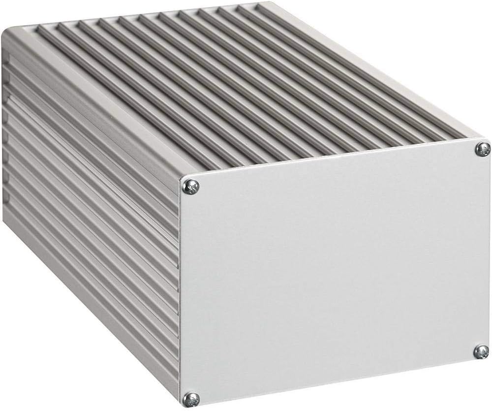
Below is the now completed enclosure for the power supply.

The front panel is the back panel from the SG502 that I'm using here as the front panel.

The top shelf has the actual instruments. From left to right: the DC Dynamic Load, the SG505, my frequency counter, and the GPSDO on top of the master clock, the rest is out of sight) BTW, these are all instruments that are listed on my Blog. Below that shelf is room for the supporting stuff, like the power supplies.

This concludes this project for the time being.
Here is the overall project Github with all the design files:
https://github.com/paulvee/DIY-Rebuild-of-the-SG505
Here is the Shared Project listing on the PCBWay website:
Shared Project DIY SG505 Power Supply