This is the start of a DIY rebuild project for the Tektronix PS503A dual tracking power supply.
I once build this unit a long time ago, in the late 70's, using several original parts.


An attempt to create my own dual supply many years later is described on my Blog here.

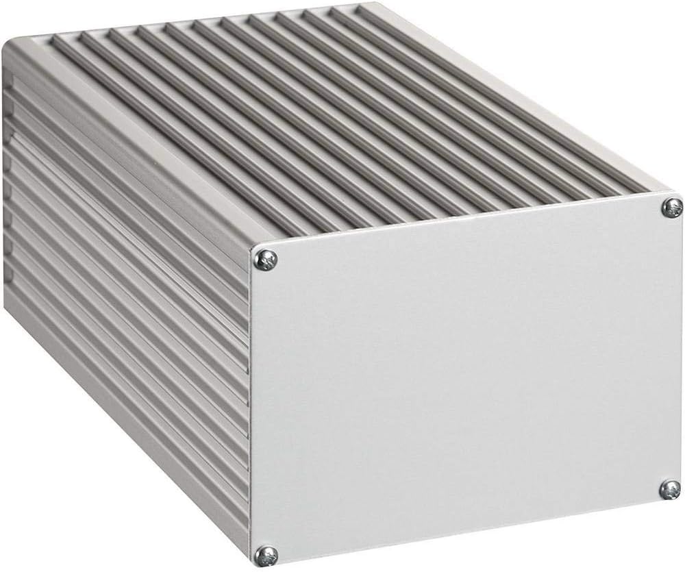
I'm showing this instrument because my plan is to use the same enclosure and the controls, but with a new PCB front panel. The PS503A does not have a display, but I'm going to use this one. After I build it, I made several changes to the way the display is used, hence the handwriting on the panel. It is actually an accurate voltmeter with an LCD. I use a switch to show either the positive or the negative voltage. The switch above with the +/-V does that. The switch labeled Tracking will tie the two supplies together such that the voltage set for the positive supply will be tracked by the negative supply. This Master-Slave method is quite common, but the Tek engineers figured out a way to select separate rail voltages and use the tracking to change the set voltages by a percentage. So you can have a rail for +15V and one for -8V and change both voltages together in a relative method, by a percentage change. That's what I will use too.
Unfortunately, the above supply, that started as a study on using the standard LM317 and LM337 regulators works OK, but not great. The main drawback is that I used a transformer that only allows +/- 100mA at 30V and the current is not enough for many of my projects.
The goals for this DIY PS503A project
The goal is to build a standalone unit that can be placed close to a prototype to supply the required rail voltages. My intention is to use this supply when I'm working with Opamps that need a positive and a negative rail.
As mentioned above, the rather special feature of the PS503A is that it not only has dual tracking, but also with two different voltages. The dual tracking in this case will supply a percentage change on both rails. More information can be found on the Tek Wiki pages here.
The SG503A goes up to +/-20V and 1A, and I'm planning to see if I can increase the voltage to +/-25V, maybe not with a 1A output, but maybe half of that above 20V. A lot will depend on the transformer, it has to fit in the enclosure. With the now selected transformer I'm limited to +/-20V, just like the original, but with a maximum current of 600mA.
The challenge with the original design of the supply is that the circuit needs Opamps that with one rail goes to the output limit plus some headroom, and also need a negative supply of several volts. This inherantly limits the maximum power supply output voltage to an output that is several Volts below the maximum Opamp +/-rail voltages. The early 741 Opamps I believe had a maximum of 36V but in reality, could not be used reliably with this limit. Most older designs I know used +/-15V rails with these Opamps.
The H-P method
More modern supplies use another method using a separate auxiliary supply for the Opamps and they regulate from the supply ground level up or down. My other Power Supply that I designed several years ago uses that method. That was actually invented by a company called Harrison that was specialising in Lab Supplies that was later purchased by H-P. The method eventually became known as the H-P method because they used it in many of their Lab Power supplies. This smart "trick" allowed engineers to build power supplies with much higher output voltages.
Applying this method to the PS503A would mean a significant demolition and reconstruction job that is beyond my plans for this supply.
Possible improvements to the PS503A
One of the items I would like to address is the over-voltage protection. The original over-voltage protection for the PS503A uses a Zener with an SCR to cut the output if it is above about 24V. That would be a catastropic failure condition. In earlier versions, like the one I originally built, the SCR would actually short the raw supply rails with a small resistor to the common such that it would blow a fuse. That's pretty dramatic, and that method is called a crow-bar circuit. In latest version of the supply however, the SCR now cuts the drive to the output transistors, and will also discharge the output capacitor. This is a clever trick because it protects the DUT in case the power transistors fail.
There are several components that do not like a dramatic disappearance of one of the rails, it could actually damage the chip. So my plan is to see if I can couple the fault mechanism to both rails at the same time. However, after thinking some more about this, I did not persue that and will not add that for this prototype.
The other improvement I would like to add is a tracking overvoltage protection, that would remove the output if the actual output voltage level is only a Volt or so higer than the set voltage, to protect my precious circuits much earlier and at lower voltages, which is especially critical for 5V and below rail voltages.
Building a simple prototype
To better understand the circuitry and try some of the enhancements or changes, I built the positive supply section and the voltage reference section on protoboard. I did that in several steps to test them out before adding more complexity.
Here is the complete positive supply section, working and functional with some improvements already. It does not have the over voltage protection yet. That was to be added later.

What you see here on the left is the original voltage reference section with an alternative I want to use. Next to it the dual +/-10V references (for both supplies) followed by the voltage controller and the output section. The red test lead in the middle is connected to the output terminal, which is the right side of the green 0.6 Ohm current sense resistor. To the left of that are the two output transistors. On the top right edge of the first board you can also see a device on a carrier which is the new current source.
The circuit on the protoboard on the right is the current controller. The red LED is lit, because I adjusted the output current with my Dynamic Load and dialed in the tripping point of the Current Limiter, such that the supply is now in the Constant Current mode. The original PS503A uses a little incandescent light bulb (18V 26mA) to show an indication of the output level voltage. I changed that circuit slightly and now use a yellow LED, and you see that lit on the right hand side. More about that below.
Improvements

Here is the positive supply section I prototyped and will be addressing below:

The reference supply
While I was building and testing the prototype, I noticed a few items that I wanted to address. First of all, I found that the reference supply is not as stable or resistant to sudden temperature changes, although it uses the classic form of temperature compensation. The engineers used a common trick by using a diode (CR24) in series with a Zener (VR24) to counter the voltage change due to temperature. (one has a positive coefficient, and the other has a negative effect) However, that does not work well with sudden changes, like a draft. It also takes quite some time to warm-up to a stable reference voltage. When I used my DMM on the reference voltage and briefly blew some of my breath over it, the voltage jumped before it slowly normalized again.

Granted, this will not happen this drastic when everything is warmed-up and inside an enclosure.
But, it's also not as stable as I would like to have it (see below), and worse, the +33V supply for this circuit will vary with the output load as I describe later. The 33V rail voltage can drop to 24V with a maximum load. The REF01 voltage reference will be better suited for these changes, but I may want to add a small circuit to keep the voltage constant. I need to test that later. The voltage reference chip that the engineers at the time most likely didn't have access to, or it was deemed too expensive, or deemed to be too good for the intended applications for this supply. I will most likely make both options available on the PCB, if there is enough room. There is not so I dropped that circuit.
Here is the schematic (in KiCad) for the VRef and Tracking circuit. On the left in the box the original voltage reference circuit and in the smaller box the new one.

The Vref of 9V, or in my case 10V is fed to the two Opamps, in a configuration where one is a voltage follower with the same output as the input, U1, to provide +10V for the negative supply, and U2 that changes the polarity to a -10V reference voltage for the positive supply. Yes, you're reading this correctly, it's not a mistake.
Here is the measurement that I took from the original reference voltage output.

This is after a warm-up period of about 15 minutes. It takes a very long time to settle. Note the span of 14.3mV over this 1hr period. This is not all together bad, but it also means that the output will swing with it, amplified by a factor of two. (10V reference amplified to get a 20V output)
The real test is to measure the output of the supply and include all components that could contribute.
Here is how that looks for a small snap-shot:

Not impressed with this, I used a REF01 10V reference chip to replace the original 9V reference, and this is the result measuring the output again:

The swings look much more dramatic, but the span is only 3.8mV, a 4x improvement and this was after a rather short warm-up with a reference that did not have a burn-in period yet.
Lets have a look at the various other building blocks of this instrument.
The positive supply

This schematic already shows my latest changes in it, explained next.
When you look at this schematic, you have to realize that the +/-VDC rail, that is actually shown as +/-33V in the original, and the +/-27V rail are not constant values. They are only accurate when there is no load on the output. Both voltages will go down with increasing loads and can get as low as 25V! See the section about the transformer selection below for details. The +/- 27V rails were only added as a limit to protect the 741 Opamps, and provide a maximum, but the voltages will get below that value with higher output currents.
Please note that this is still under development so can easily change. I will do my best to update the schematics as I'm progressing, but don't use them yet to build your own, give me some time to complete it first. There is now a 2.7R resistor from the cathode of Q15 to GDN, and D29 is now a 1N5401, a 2A part instead of the 1A original.
The improvements I already made
The Opamps
Instead of one of the first available Opamps, the 741 Opamps that were used in the earlier generations, I selected the TLE2141 Opamps. Mainly because I have many of them, and they can stand a 44V supply maximum, which makes it more reliable than the originals that went kaduk quite often. Even so much so that lower (+/-27V) protection rails were added to the PS503 design, and even that did not stop all the failures. This could also be contributed to the fact that the early 741's were not that reliable stemming from earlier manufacturing processes. I could have use the TL071, but that also has a rather limited maximum supply voltage specification. As a minimum, during the prototyping phase, I will be using the more rail tolerant TLE2141. It also allows me to raise the +/-6V2 voltages to +/-8V by using regulators. I have some 36V uA741CP on order so I can try the more modern versions as well (with adjusted rails). There are modern versions of the 741 available that have a 44V rail maximum, but they were not available through my preferred sources.
When you use the relatively slow 741's, you dont need frequency compensation to prevent instability or oscillations. My plan is to test them with the first prototype.
The current source/bias for the diode OR and output transistor
This step is a pre-cursor requirement for increasing the supply voltage and is better because it removes the effect of the rail swings due to the load as well.
If you look at the original schematic, I replaced the bias setting resistor (R87) to the Base of the driving transistor Q14 from a 3K resistor to a 5mA Current Sink. This will make the diode OR circuit and Base current independent of the raw supply and the variable current flow when the output voltage is changed from the minimum to the maximum. In the 20V version, that point moves from 9V to about 25V, and hence the Base current changes for Q14.
The just about standard method is to use a current source and not a resistor. In my previous design for a power supply, I used a typical circuit to create a stable current source.
Below is that circuit. It used a red LED as a rather stable voltage source to bias the PNP transistor Q2. The Emitter resistor R4 sets the current, R15 sets the LED current. The capacitor of 220uF was added as a startup glitch protection, because it delayed the bias setting until the other supplies where stable.
In that supply design, I used LED's as the diode OR because they were used on the front panel showing the CV or CC mode activity.

There are many other possibilities to create a current sink/source, but I opted to use a dedicated LTC chip (LT3092) and two resistors to precisely set the current. I already had two of them in my stash, waiting to be used. I tried it out and it works really well. By using the formula in the datasheet, I could easily select the resistor value for the 5 mA current I wanted. This is a little higher than the original current that varied between 1.7mA and 4.9mA using the resistor, but that is not very critical.
The Vref for the current limiter
Because I'm now using a different VRef circuit, I needed to change the Voltage reference for the current limit circuit. In the original, that voltage was tapped from the VRef circuit (connection between R28 and R29), and then fed through a diode (CR78) to the base of Q80. I simply adopted the circuit from the negative supply and used that for the positive supply as well. This adds R41, Q11 and R40 in my schematic.
I noticed that by changing the unregulated supply voltage, the collector voltage of Q3 supplying the CL potmeter is changing only a few mV between 33V (no load) and 25V (maximum load), keeping the voltage across the CL potmeter quite constant at 750mV for the 400mA output load setting, but needs to be checked again when I will go to a higher output voltage from 20V to 30V, or the full 1A current. It may need a voltage regulator or current sink.
The Voltage output indicator
Because I don't want to use a light bulb for the Voltage indicator (old school), I'm using an LED that many users of the PS503A had to change to as well because these tiny bulbs are now hard to get. I opted for a yellow LED, and that required a value change for two resistors, R14 from 5K6 to 15K and R15 from 510R to 160K in my schematic. Both values depend on the LED current, so may need some tweaking with different LED's. I'm simply using one that I already have, but is without specifications. In my case, the LED is just off with a zero Volt output and will be bright at 20V. When the output is switched off with SW2, the current from R15 is disconnected and the LED is off to show you that there is no output voltage present. Just like the original. When the overvoltage protection kicks in, the output goes to zero V and that also turns off the LED.
Decoupling the Opamps
I also added decoupling capacitors for the Opamp rails.
Sziklai output transistor pair
The last change, for the time being, is the change of the Sziklai output transistor pair. In the original, the power transistor was in the TMXXX mainframe and is not so easy to find. I selected a combination of the BD139 and the D45H11. I had a few left from my Walt Jung voltage regulator design, and if Walt found this transistor good enough, who am I to disagree? This selection may change however when I have a real setup that will allow me to do some power stress tests later on.
If you want to know more about this Sziklai configuration and the difference or pro & cons compared with a Darlington pair, use Google.
There are two main differences that I care about. First of all the input voltage for the first transistor is 0.6V for the Sziklai and double that or 1.2V for the Darlington combo. The other difference is the thermal stability that is reportedly better with the Sziklai, and the two transistors do not need to be on the same heat sink, which was important for the original PS503A with the output transistor located in the TM5XX mainframe. The original TM5XX mainframes used the TO220 versions of the 3055 and 2955 transistors. More information about these transistors and replacements can be seen here.
Resistor value changes
Although I purchased all the required (odd) resistor values, I may change several of them to the E96 range. The reason Tek used these sometimes odd ball values, like 1K05 or 1K62 and 976 Ohm is that in those days, through-hole metal film 1% or better resistors only came in these values (not even in E192).
The BOM will show some of the alternatives.
The over voltage protection

D29 is now a higher current 1N5401.
The tracking overvoltage protection

I'm using U13 as a comparator to determine the tripping point. The output of the voltage regulator Opamp U7 is used as the reference voltage for U13. The output of U7 has almost the same voltage as the output, so varies between 0..20V. I'm also tapping the output terminal and drop that voltage by two diodes in series to create a delta between the output and the set voltage. C51 and R52 are there to provide a bias for the diodes and also a filter.
The negative supply


The Power rails
Transformer selection challenges
So what are the effects of my 24VAC 30VA transformer?

What you see on the protoboard is the bridge, a bleeder resistor on the bottom, the main capacitor, a 1 Ohm series resistor, changed from the 2R2 resistor I wanted to use, and a 2,200uF for the second capacitor, replacing the 1,000uF I wanted to use. The 2R2 got too hot, and the 1 Ohm was sufficient. The increase in the second capacitor dropped the ripple quite substantially, also making up for the reduction in the resistor. The second capacitor and the 1R resistor might not be needed for the 500mA version, but I leave it in as an option for the 1A version.
Supporting a 1A output

To the right is the new 2x25VAC with 1.6A toroid with 80VA. It is significantly larger and weighs just over 1Kg. The one on the left weighs 532gr. The heatsink will have to be mounted on the outside of the back panel, if the back panel itself is not sufficient to have enough room for the PCB. I will use the room that the 80VA will leave as the size for the PCB.
Power rail schematic

The Voltmeter

This circuit is quite simple but in order to switch the display voltmeter inputs around so we can measure the positive and the negative supplies, the power rails for the meter have to be galvanically isolated from the rest of the circuits, hence the small additional transformer. The minus input from the voltmeter is internally connected to the minus supply voltage of the meter/display, so that's why this is needed.
Next steps
Now that I have the inner workings understood (at least I think so), and verified most of the enhancements with the prototypes, I think I'm ready now with a first attempt on designing a PCB. With that comes all the sorting out of the components and footprints, so that will take some time.
I have the layout of the main board done and I'm now working on the front panel which will be a PCB as well. The layout of the controls on the rather busy front panel required a few changes to the main PCB, so I'm going back and forth to make sure it all fits the first time. I hope...
There are also some changes to the circuits and I will post the latest schematic diagrams, and screen shots of the PCB's below.
Here is the completed layout of the PCB.

I'm using TO-92 packages for the transistors so I can easily swap them out for other types if required. When that is done I could switch them out with SMD versions with a new board revision.
And here is a 3D view of the front panel - note that it will have a black solder mask:

There is a ground fill on the front and back to act as a shield and will also add some sturdiness and produce a very nice half-matt black finish. All the holes are plated through with a larger surface on the back to properly ground all potmeters and switches. The four LED's have a normal 3mm hole. I decided to not implement a LED indicating the low current setting (300mA). It's obvious from the switch setting, and the front panel is already very busy.
Another thing you may miss is the switch to activate the dual tracking feature. I found an original potmeter with the switch at a site that sells Tektronix parts, and I purchased one. Not having a switch is not that cumbersome, because you can turn the potmeter fully CW (fully up in the diagram) to the 100% setting, and that will actually be the same as using the switch.
Here are the latest schematic diagrams with the latest changes. The updated Voltmeter section is just above.

Not many changes, but I did ad a jumper to deactivate the tracking overvoltage circuit in both supplies.


At first I had room on the PCB to implement the original reference circuit, but I found out that I needed more room close to the front panel for the current potmeters. Eliminating that board space made it too cumbersome to move that circuit someplace else, now that the rest of the layout was already done, so I took it out.
Mechanical construction
Below is the old front panel that will be replaced by the new PCB. The paper copy shows the dimensions of the main PCB inside the enclosure, with now plenty of room for the potmeters and the three 4mm binding posts in the front.
The bottom side of the board with the bridges and output transistors, will be mounted flush on the metal back panel for cooling. To the right is room for the mains input receptacle and filter. The main transformer will be mounted on the top half of the enclosure, hanging down so to speak. If the cooling of the back panel alone is not sufficient, I will add a heatsink mounted to the back panel on the outside of the enclosure. At least that is the plan.

The two boards are now uploaded to my sponsor PCBWay, and I hope they will accept to sponsor this project as usual. They did, so the two boards are now in production. As soon as I have the boards, I will continue with the project.
While waiting for the PCB's, I looked at a way to replace the two rail fuses (F1, F2) by something else. During the prototyping phase, I'm using PTC fuses, but they are pretty slow to react. Glass fuses can be much faster but are destructive, you have to open the unit to replace them. I'm now looking into using MOSFET's that will be driven by the two fault conditions. They are much faster, and are non-destructive. As soon as I have the prototype working on the new PCB I will experiment some more with that possibility.
Keep coming back regularly, I will be adding or changing information as I go about designing the rest of the project.
More later....